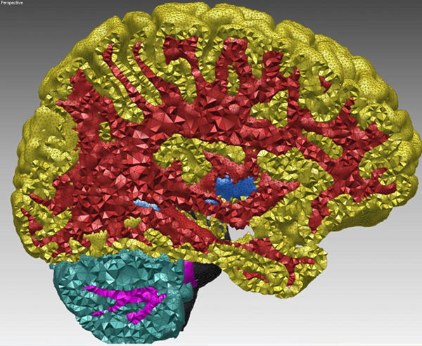
Figure 47.1: Cut-view of a multi-domain 3D mesh generated from a segmented image.
47.1 Introduction
This package is devoted to the generation of isotropic tetrahedron meshes discretizing 3D domains. The main entry points of this component are two global functions that respectively generate and refine such meshes. The domain to be discretized may be formed either by a single connected component or by several connected components. We refer to the domain as a multi-domain when the different components need to be identified as different subdomains. The mesh generator generates at once a simplicial 3D mesh which includes one submesh for each subdomain and surface meshes which approximate the boundaries of the domain and subdomains.
Input domain
More specifically, the domain to be discretized is assumed to be representable as a pure 3D complex. A 3D complex is a set of faces with dimension 0 (vertices), 1 (edges), 2 (facets) and 3 (cells) such that all faces are pairwise interior disjoint, and the boundary of each face of the complex is the union of faces of the complex. The 3D complex is pure, meaning that each face is included in a face of dimension 3, so that the complex is entirely described as a set of 3D cells. The set of faces with dimension lower or equal than 2 form a 2D subcomplex. In the rest of the documentation, we will refer to the input 3D complex as to the input domain.
Note that the input complex faces are not required to be linear. Facets, for instance, are typically smooth surface patches, or portion of surface meshes with boundaries. The mesh generator provides at the same time a 3D mesh discretizing each of the complex cells and a surface mesh approximating the 2D complex that describes cell boundaries. In its current state the mesh generator does not handle sharp creases in the domain description. This does not mean that the domain to be meshed and its subdomains are required to have smooth boundary surfaces. The domain and subdomains boundaries may be provided as smooth patches joined along sharp edges. However, currently, the mesh generator does not take into account the edge description and hence those edges are not accurately represented by a sequence of mesh edges.
The mesh generator is able to handle multiple junctions where three or more subdomains meet. Consequently the generated surface mesh may be non-manifold as a whole, even if each submesh approximating the boundary of a subdomain is manifold.
The domain is input to the mesh generation function, as a class devised to answer queries about the domain as well as its subdomains. Mainly, this class provides predicates which state if a given query point belongs to the domain or not, and in the affirmative, to which of the subdomains it belongs to. Current implementation provides classes to represent domains defined by implicit functions, polyhedral domains and domain defined through 3D labeled images.
Output mesh
The resulting mesh is output as a subcomplex of a 3D triangulation, in a class providing various iterators on mesh elements. The 3D triangulation provides an approximation of the domain, subdomains and their boundaries, according to the restricted Delaunay triangulation paradigm. This means that the domain (resp. each subdomain) is approximated by the union of the tetrahedral cells whose circumcenters are located inside the domain (resp. inside the subdomain). Each surface patch of the domain or subdomains boundary is approximated by the union of the Delaunay facets whose dual Voronoi edges intersect the surface patch. Such facets are called in the following surface facets or boundary facets.
The mesh generation algorithm is a Delaunay refinement process followed by an optimization phase, which is currently implemented using the sliver exudation approach [CDE+00]. The Delaunay refinement process is driven by criteria concerning either the mesh cells or the surface facets. The refinement process terminates when there are no more mesh cells or surface facets violating the user-specified criteria. The Delaunay refinement eliminates all kind of quasi degenerate tetrahedra except slivers. At the end of the refinement process, some sliver shaped tetrahedra may occur in the mesh. The optimization phase aims at eliminating slivers.
The criteria can be tuned to achieve the user needs with respect to the size of mesh elements, the accuracy of boundary approximation and topological conditions. The default criteria for surface facets are governed by the three following parameters:
- the angular bound: This parameter controls the shape of surface facets. Actually, it is a lower bound for the angle (in degree) of surface mesh facets. The termination of the meshing process is garanted if the angular bound is at most 30 degrees.
- the radius bound: This parameter controls the size (edge length) of surface facets. Actually, each surface facet has a surface Delaunay ball which is a ball circumscribing the surface facet and centered on the surface patch. The radius bound is an upper bound on the radii of surface Delaunay balls.
- the distance bound: This parameter controls the approximation error of the surface. Actually, it is an upper bound for the distance between the circumcenter of a surface facet and the center of a surface Delaunay ball of this facet.
The default criteria for mesh cells are governed by two parameters:
- the radius-edge bound: This parameter controls the shape of mesh cells (but can't filter slivers, as we discuss earlier). Actually, it is an upper bound for the ratio between the circumradius of a mesh tetrahedron and its shortest edge.
- the radius bound: This parameter controls the size (edge length) of mesh cells. Actually, it is an upper bound on the circumradii of the mesh tetrahedra.
Figure 47.2 shows how the mesh generation process behaves with respect to these parameters.
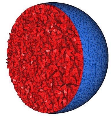
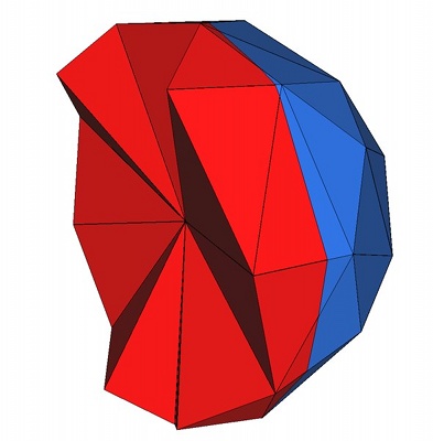
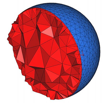
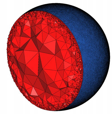
Figure 47.2: Top : the mesh is obtained using the parameters (25,0.15,0.05) for the angular bound, radius bound and distance bound of surface facets and (4,0.2) for the radius-edge bound and radius bound of mesh cells. The result is a uniform mesh which contain tetrahedra of about the same size. Bottom left : the mesh is obtained by releaxing the size bound of tetrahedra and facets. The result is a small coarse mesh. Bottom middle : the mesh is obtained from the previous one by tightening the distance bound of surface facets to 0.01. The result is then a graded 3D mesh with a dense surface mesh achieving a precise approximation. Bottom right : the mesh is obtained from the previous one by fixing radius bound of surface facets to to 0.01. The surface mesh is then denser to achieve the size bound.
47.2 Interface
A 3D mesh generation process is called through a call to one of the two following functions:
The function make_mesh_3 generates from scratch a mesh of the input domain, while the function refine_mesh_3 refines an existing mesh of the input domain.
The template parameter C3T3 is required to be a model of the concept MeshComplex_3InTriangulation_3, a data structure devised to represent a three dimensional complex embedded in a 3D triangulation. In both functions, an instance of type C3T3 is used to maintain the current approximating simplicial mesh of the domain and subdomains and to represent the final 3D mesh at the end of the procedure. The type C3T3 is required to provide a nested type C3T3::Triangulation_3 for the 3D triangulation embedding the mesh. This triangulation is required to be a regular triangulation. The vertex and cell base classes of the triangulation C3T3::Triangulation_3 are required to be respectively models of the concepts MeshVertexBase_3 and MeshCellBase_3.
The template parameter MeshDomain is required to be a model of the concept MeshDomain_3. The argument mesh_domain of type MeshDomain is the sole link through which the domain to be discretized is known by the mesh generation algorithm. The concept MeshDomain_3 is similar to the concept SurfaceMeshTraits defined by the surface mesh generation package. This concept provides, among others, member functions to test whether or not a query segment intersects boundary surfaces, and to compute an intersection point in the affirmative. The MeshDomain_3 concept adds member functions which given a query point tell whether the point lies inside or outside the domain and in which subdomain the point lies if inside.
The template parameter MeshCriteria must be a model of the concepts MeshCriteria_3. The argument of type MeshCriteria passed to the mesh generator specifies the size and shape requirements for the tetrahedra in the mesh and for the triangles in the boundary surface mesh. These criteria form the rules which drive the refinement process. At the end of the refinement process, every mesh element satisfy those criteria. This may not be true anymore after the sliver removal phase although this last phase is devised to only improve the mesh quality.
47.3 Examples
47.3.1 Mesh Generation From an Implicit Domain
The following code produces a 3D mesh for a monodomain whose boundary surface is defined by an implicit function. Figure 47.3 shows a cut view of the resulting mesh.
File: examples/Mesh_3/mesh_implicit_sphere.cpp
#include <CGAL/Exact_predicates_inexact_constructions_kernel.h>

#include <CGAL/Mesh_triangulation_3.h>
#include <CGAL/Mesh_complex_3_in_triangulation_3.h>
#include <CGAL/Mesh_criteria_3.h>

#include <CGAL/Implicit_mesh_domain_3.h>
#include <CGAL/make_mesh_3.h>

// Domain
struct K: public CGAL::Exact_predicates_inexact_constructions_kernel {};
typedef K::FT FT;
typedef K::Point_3 Point;
typedef FT (Function)(const Point&);
typedef CGAL::Implicit_mesh_domain_3<Function,K> Mesh_domain;

// Triangulation
typedef CGAL::Mesh_triangulation_3<Mesh_domain>::type Tr;
typedef CGAL::Mesh_complex_3_in_triangulation_3<Tr> C3t3;

// Criteria
typedef CGAL::Mesh_criteria_3<Tr> Mesh_criteria;
typedef Mesh_criteria::Facet_criteria Facet_criteria;
typedef Mesh_criteria::Cell_criteria Cell_criteria;

// Function
FT sphere_function (const Point& p)
{
  const FT x2=p.x()*p.x();
  const FT y2=p.y()*p.y();
  const FT z2=p.z()*p.z();

  return x2+y2+z2-1;
}

int main()
{
  // Domain (Warning: Sphere_3 constructor uses square radius !)
  Mesh_domain domain(sphere_function, K::Sphere_3(CGAL::ORIGIN, 2.));

  // Criteria
  Facet_criteria facet_criteria(30, 0.1, 0.025); // angle, size, approximation
  Cell_criteria cell_criteria(3, 0.1); // radius-edge ratio, size
  Mesh_criteria criteria(facet_criteria, cell_criteria);

  // Mesh generation
  C3t3 c3t3 = CGAL::make_mesh_3<C3t3>(domain, criteria);

  // Output
  std::ofstream medit_file("out.mesh");
  c3t3.output_to_medit(medit_file);

  return 0;
}
Figure 47.3: Cut-View of a 3D mesh produced from an implicit domain
47.3.2 Mesh Generation From a Polyhedral Domain
The following code produces a 3D mesh for a monodomain defined by polyhedral surfaces. Figure 47.4 shows the resulting mesh.
File: examples/Mesh_3/mesh_polyhedral_domain.cpp
#include <CGAL/AABB_intersections.h>
#include <CGAL/Exact_predicates_inexact_constructions_kernel.h>
#include <CGAL/Mesh_3/Robust_intersection_traits_3.h>

#include <CGAL/Mesh_triangulation_3.h>
#include <CGAL/Mesh_complex_3_in_triangulation_3.h>
#include <CGAL/Mesh_criteria_3.h>

#include <CGAL/Polyhedral_mesh_domain_3.h>
#include <CGAL/make_mesh_3.h>
#include <CGAL/refine_mesh_3.h>

// IO
#include <CGAL/IO/Polyhedron_iostream.h>

// Domain
// (we use exact intersection computation with Robust_intersection_traits_3)
struct K: public CGAL::Exact_predicates_inexact_constructions_kernel {};
typedef CGAL::Mesh_3::Robust_intersection_traits_3<K> Geom_traits;
typedef CGAL::Polyhedron_3<Geom_traits> Polyhedron;
typedef CGAL::Polyhedral_mesh_domain_3<Polyhedron, Geom_traits> Mesh_domain;

// Triangulation
typedef CGAL::Mesh_triangulation_3<Mesh_domain>::type Tr;
typedef CGAL::Mesh_complex_3_in_triangulation_3<Tr> C3t3;

// Mesh Criteria
typedef CGAL::Mesh_criteria_3<Tr> Mesh_criteria;
typedef Mesh_criteria::Facet_criteria Facet_criteria;
typedef Mesh_criteria::Cell_criteria Cell_criteria;

int main()
{
  // Create polyhedron
  Polyhedron polyhedron;
  std::ifstream input("data/elephant.off");
  input >> polyhedron;

  // Create domain
  Mesh_domain domain(polyhedron);

  // Set mesh criteria
  Facet_criteria facet_criteria(25, 0.15, 0.008); // angle, size, approximation
  Cell_criteria cell_criteria(4, 0.2); // radius-edge ratio, size
  Mesh_criteria criteria(facet_criteria, cell_criteria);

  // Mesh generation
  C3t3 c3t3 = CGAL::make_mesh_3<C3t3>(domain, criteria);

  // Output
  std::ofstream medit_file("out.mesh");
  c3t3.output_to_medit(medit_file);
  medit_file.close();

  // Change tetrahedron size
  Cell_criteria new_cell_criteria(4, 0.03); // radius-edge ratio, size
  Mesh_criteria new_criteria(facet_criteria, new_cell_criteria);

  // Mesh refinement
  CGAL::refine_mesh_3(c3t3, domain, new_criteria);

  // Output
  medit_file.open("out_1.mesh");
  c3t3.output_to_medit(medit_file);

  return 0;
}
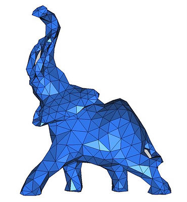
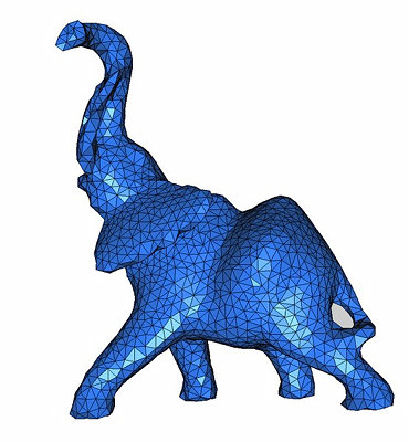
Figure 47.4: View of 3D meshes produced from a polyhedral domain. (i) is a view of file out_1.mesh and (ii) is a view of file out_2.mesh. Code from subsection 47.3.2 generates these files.
47.3.3 Mesh Generation From a Segmented 3D Image
The following code produces a 3D mesh from a 3D image. The image is a segmented medical image in which each voxel is associated a label in accordance with the tissue the voxel belongs to. The domain is therefore a multi-domain where each subdomain corresponds to a specific tissue. The resulting mesh is shown in Figure 47.5.
File: examples/Mesh_3/mesh_3D_image.cpp
#include <CGAL/Exact_predicates_inexact_constructions_kernel.h>

#include <CGAL/Mesh_triangulation_3.h>
#include <CGAL/Mesh_complex_3_in_triangulation_3.h>
#include <CGAL/Mesh_criteria_3.h>

#include <CGAL/Labeled_image_mesh_domain_3.h>
#include <CGAL/make_mesh_3.h>
#include <CGAL/Image_3.h>

// Domain
struct K: public CGAL::Exact_predicates_inexact_constructions_kernel {};
typedef CGAL::Image_3 Image;
typedef CGAL::Labeled_image_mesh_domain_3<Image,K> Mesh_domain;

// Triangulation
typedef CGAL::Mesh_triangulation_3<Mesh_domain>::type Tr;
typedef CGAL::Mesh_complex_3_in_triangulation_3<Tr> C3t3;

// Mesh Criteria
typedef CGAL::Mesh_criteria_3<Tr> Mesh_criteria;
typedef Mesh_criteria::Facet_criteria    Facet_criteria;
typedef Mesh_criteria::Cell_criteria     Cell_criteria;

int main()
{
  // Loads image
  Image image;
  image.read("data/liver.inr.gz");

  // Domain
  Mesh_domain domain(image);

  // Mesh criteria
  Facet_criteria facet_criteria(30, 6, 4); // angle, size, approximation
  Cell_criteria cell_criteria(3, 8); // radius-edge ratio, size
  Mesh_criteria criteria(facet_criteria, cell_criteria);

  // Meshing
  C3t3 c3t3 = CGAL::make_mesh_3<C3t3>(domain, criteria);

  // Output
  std::ofstream medit_file("out.mesh");
  c3t3.output_to_medit(medit_file);

  return 0;
}
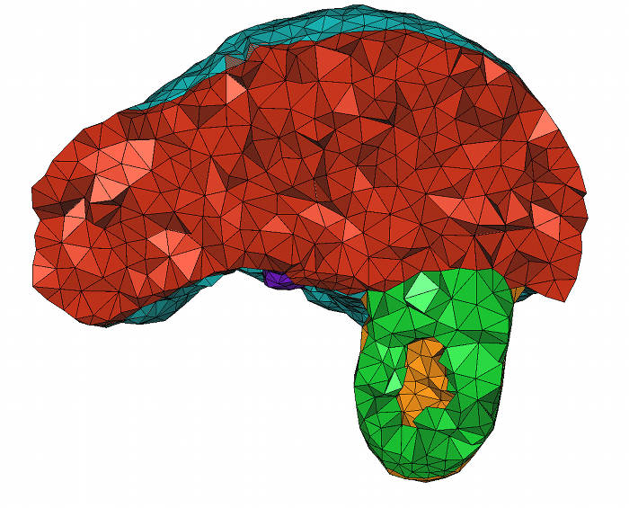
Figure 47.5: Cut-view of a 3D mesh produced from a segmented liver image. Code from subsection 47.3.3 generates this file.