|
CGAL 4.9.1 - 2D Triangulation Data Structure
|
|
CGAL 4.9.1 - 2D Triangulation Data Structure
|
A triangulation data structure is a data structure designed to handle the representation of a two dimensional triangulation. The concept of triangulation data structure was primarily designed to serve as a data structure for CGAL 2D triangulation classes which are triangulations embedded in a plane. However it appears that the concept is more general and can be used for any orientable triangulated surface without boundary, whatever may be the dimensionality of the space the triangulation is embedded in.
The representation of CGAL 2D triangulations is based on faces and vertices, Edges are only implicitly represented trough the adjacency relations between two faces.
The triangulation data structure can be seen as a container for faces and vertices maintaining incidence and adjacency relations among them.
Each triangular face gives access to its three incident vertices and to its three adjacent faces. Each vertex gives access to one of its incident faces and through that face to the circular list of its incident faces.
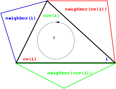
The three vertices of a face are indexed with 0, 1 and 2. The neighbors of a face are also indexed with 0,1,2 in such a way that the neighbor indexed by i is opposite to the vertex with the same index. See Figure 38.1, the functions ccw(i) and cw(i) shown on this figure compute respectively \( i+1\) and \( i-1\) modulo 3.
Each edge has two implicit representations: the edge of a face f which is opposed to the vertex indexed i, can be represented as well as an edge of the neighbor(i) of f.

This kind or representation of simplicial complexes extends in any dimension. More precisely, in dimension \( d\), the data structure will explicitly represents cells (i. e. faces of maximal dimension) and vertices (i. e. faces of dimension 0). All faces of dimension between \( 1\) and \( d-1\) will have an implicit representation. The 2D triangulation data structure can represent simplicial complexes of dimension 2, 1 or 0.
The set of faces maintained by a 2D triangulation data structure is such that each edge is incident to two faces. In other words, the set of maintained faces is topologically equivalent to a two-dimensional triangulated sphere.
This rules extends to lower dimensional triangulation data structure arising in degenerate cases or when the triangulations have less than three vertices. A one dimensional triangulation structure maintains a set of vertices and edges which forms a ring topologically equivalent to a \( 1\)-sphere.
A zero dimensional triangulation data structure only includes two adjacent vertices that is topologically equivalent to a \( 0\)-sphere.
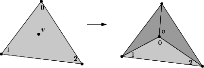
A model of TriangulationDataStructure_2 can be seen has a container for the faces and vertices of the triangulation. This class is also responsible for the combinatorial integrity of the triangulation. This means that the triangulation data structure maintains proper incidence and adjacency relations among the vertices and faces of a triangulation while combinatorial modifications of the triangulation are performed. The term combinatorial modification refers to operations which do not involve any knowledge about the geometric embedding of the triangulation. For example, the insertion of a new vertex in a given face, or in a given edge, the suppression of a vertex of degree three, the flip of two edge are examples of combinatorial operation performed at the data structure level.
The triangulation data structure is required to provide:
Vertex and Face for the vertices and faces of the triangulations Vertex_handle and Face_handle which are models of the concept Handle and through which the vertices and faces are accessed. The triangulation data structure is responsible for the creation and removal of faces and vertices (memory management). It provides function that gives the number of faces, edges and vertices of the triangulation.
The triangulation data structure provides member functions to perform the following combinatorial transformation of the triangulation:

CGAL provides the class Triangulation_data_structure_2<Vb,Fb> as a default triangulation data structure.
In order to provide flexibility, the default triangulation data structure is templated by two parameters which stand respectively for a vertex base class and a face base class. The concept TriangulationDSVertexBase_2 and TriangulationDSFaceBase_2 describe the requirements for the vertex and face classes of a triangulation data structure.
This design allows the user to plug in the triangulation data structure his own vertex or face classes tuned for his application.
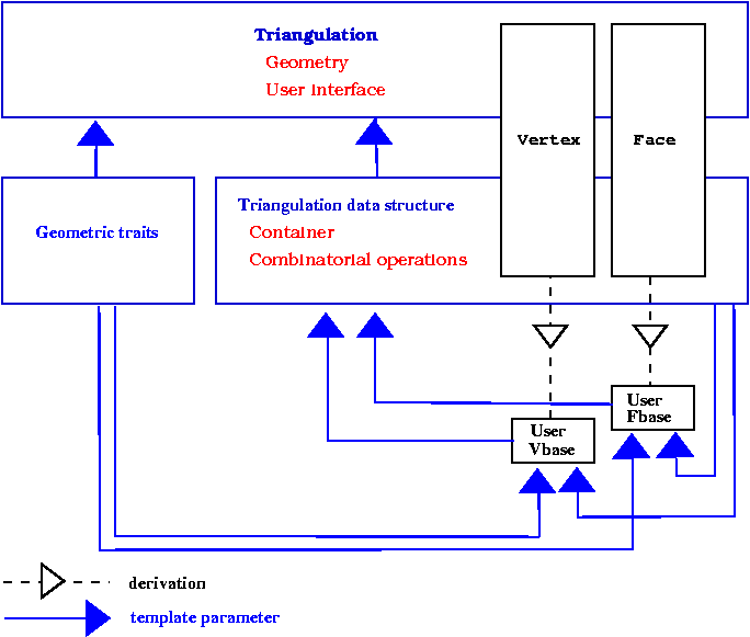
Since adjacency and incidence relation are stored in vertices and faces, the vertex and face classes have to know the types of handles on faces and vertices provided by the triangulation data structure. Therefore, vertex and face classes need to be templated by the triangulation data structure. Because the triangulation data structure is itself templated by the vertex and face classes this induces a cyclic dependency. See Figure 38.3.

The solution proposed by CGAL to resolve this cyclic dependency is based on a rebind mechanism similar to the mechanism used in the standard allocator class std::allocator. The vertex and face classes plugged in the instantiation of a triangulation data structure are themselves instantiated with a fake data structure. The triangulation data structure will then rebind these classes, plugging itself at the place of the fake data structure, before using them to derive the vertex and face classes. The rebinding is performed through a nested template class Rebind_TDS in the vertex and face class, which provide the rebound class as a type called Other.
Here is how it works schematically. First, here is the rebinding taking place in the triangulation data structure.
Then, here is the vertex class with its nested Rebind_TDS template class and its template parameter set by default to an an internal type faking a triangulation data structure.
Imagine an analog Face_base class. The triangulation data structure is then instantiated as follows:
There are several possibilities to make use of the flexibility offered by the triangulation data structure.
Triangulation_vertex_base_with_info_2 and Triangulation_face_base_with_info_2 can be plugged in. Those classes have a template parameter Info to be instantiated by a user defined type. They store a data member of this type and gives access to it. Second, the user can derive his own base classes from the default base classes: Triangulation_ds_vertex_base_2, and Triangulation_ds_face_base_2 are the default base classes to be plugged in a triangulation data structure used alone. Triangulation classes requires a data structure in which other base classes have been plugged it. The default base classes for most of the triangulation classes are Triangulation_vertex_base_2, and Triangulation_face_base_2 are the default base classes to be used when the triangulation data structure is plugged in a triangulation class.
When derivation is used, the rebind mechanism is slightly more involved, because it is necessary to rebind the base class itself. However the user will be able to use in his classes references to types provided by the triangulation data structure. For example,
TriangulationDSVertexBase_2 and TriangulationDSFaceBase_2. If the triangulation data structure is plugged into a triangulation class, the concepts for the vertex and base classes depends on the triangulation class. The most basic concepts, valid for basic and Delaunay triangulations are TriangulationVertexBase_2 and TriangulationFaceBase_2. See Section Flexibility of the chapter on 2D triangulations for examples which make use of the flexilibity of the triangulation data structure.