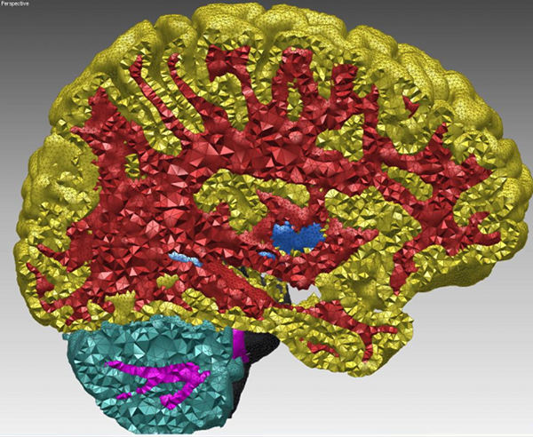
Figure 49.1: Cut-view of a multi-domain 3D mesh generated from a segmented image.
49.1 Introduction
This package is devoted to the generation of isotropic tetrahedron meshes discretizing 3D domains. The main entry points of this component are two global functions that respectively generate and refine such meshes. The domain to be discretized may be formed either by a single connected component or by several connected components. We refer to the domain as a multi-domain when the different components need to be identified as different subdomains. The mesh generator generates at once a simplicial 3D mesh which includes one submesh for each subdomain and surface meshes which approximate the boundaries of the domain and subdomains.
Input domain
More specifically, the domain to be discretized is assumed to be representable as a pure 3D complex. A 3D complex is a set of faces with dimension 0 (vertices), 1 (edges), 2 (facets) and 3 (cells) such that all faces are pairwise interior disjoint, and the boundary of each face of the complex is the union of faces of the complex. The 3D complex is pure, meaning that each face is included in a face of dimension 3, so that the complex is entirely described as a set of 3D cells. The set of faces with dimension lower or equal than 2 form a 2D subcomplex. In the rest of the documentation, we will refer to the input 3D complex as to the input domain.
Note that the input complex faces are not required to be linear. Facets, for instance, are typically smooth surface patches, or portion of surface meshes with boundaries. The mesh generator provides at the same time a 3D mesh discretizing each of the complex cells and a surface mesh approximating the 2D complex that describes cell boundaries. In its current state the mesh generator does not handle sharp creases in the domain description. This does not mean that the domain to be meshed and its subdomains are required to have smooth boundary surfaces. The domain and subdomains boundaries may be provided as smooth patches joined along sharp edges. However, currently, the mesh generator does not take into account the edge description and hence those edges are not accurately represented by a sequence of mesh edges.
The mesh generator is able to handle multiple junctions where three or more subdomains meet. Consequently the generated surface mesh may be non-manifold as a whole, even if each submesh approximating the boundary of a subdomain is manifold.
The domain is input to the mesh generation function, as a class devised to answer queries about the domain as well as its subdomains. Mainly, this class provides predicates which state if a given query point belongs to the domain or not, and in the affirmative, to which of the subdomains it belongs. The current implementation provides classes to represent domains defined by implicit functions, polyhedral domains and domains defined through 3D labeled images.
Output mesh
The resulting mesh is output as a subcomplex of a 3D triangulation, in a class providing various iterators on mesh elements. The 3D triangulation provides an approximation of the domain, subdomains and their boundaries, according to the restricted Delaunay triangulation paradigm. This means that the domain (resp. each subdomain) is approximated by the union of the tetrahedral cells whose circumcenters are located inside the domain (resp. inside the subdomain). Each surface patch of the domain or subdomains boundary is approximated by the union of the Delaunay facets whose dual Voronoi edges intersect the surface patch. Such facets are called in the following surface facets or boundary facets.
Delaunay refinement
The mesh generation algorithm is a Delaunay refinement process followed by an optimization phase. The Delaunay refinement process is driven by criteria concerning either the mesh cells or the surface facets. The refinement process terminates when there are no more mesh cells or surface facets violating the user-specified criteria. The Delaunay refinement eliminates all kind of badly shaped tetrahedra except slivers. At the end of the refinement process, some sliver shaped tetrahedra may occur in the mesh. The optimization phase aims at eliminating slivers.
The criteria can be tuned to achieve the user needs with respect to the size of mesh elements, the accuracy of boundary approximation and topological conditions. The default criteria for surface facets are governed by the three following parameters:
- the angular bound: This parameter controls the shape of surface facets. Actually, it is a lower bound for the angle (in degree) of surface mesh facets. The termination of the meshing process is guaranteed if the angular bound is at most 30 degrees.
- the radius bound: This parameter controls the size (edge length) of surface facets. Actually, each surface facet has a surface Delaunay ball which is a ball circumscribing the surface facet and centered on the surface patch. The radius bound is an upper bound on the radii of surface Delaunay balls.
- the distance bound: This parameter controls the approximation error of the surface. Actually, it is an upper bound for the distance between the circumcenter of a surface facet and the center of a surface Delaunay ball of this facet.
The default criteria for mesh cells are governed by two parameters:
- the radius-edge bound: This parameter controls the shape of mesh cells (but can't filter slivers, as we discussed earlier). Actually, it is an upper bound for the ratio between the circumradius of a mesh tetrahedron and its shortest edge.
- the radius bound: This parameter controls the size (edge length) of mesh cells. Actually, it is an upper bound on the circumradii of the mesh tetrahedra.
Figure 49.2 shows how the mesh generation process behaves with respect to these parameters.
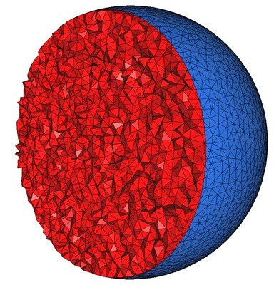
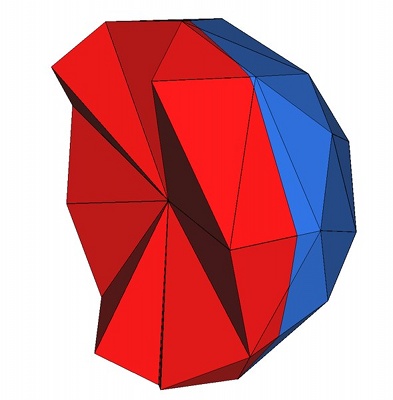
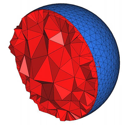
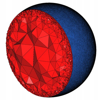
Figure 49.2: Top : the mesh is obtained using the parameters (25,0.15,0.05) for the angular bound, radius bound and distance bound of surface facets and (4,0.2) for the radius-edge bound and radius bound of mesh cells. The result is a uniform mesh which contains tetrahedra of about the same size. Bottom left : the mesh is obtained by relaxing the size bound of tetrahedra and facets. The result is a small coarse mesh. Bottom middle : the mesh is obtained from the previous one by tightening the distance bound of surface facets to 0.01. The result is then a graded 3D mesh with a dense surface mesh achieving a precise approximation. Bottom right : the mesh is obtained from the previous one by fixing radius bound of surface facets to 0.01. The surface mesh is then denser to achieve the size bound.
Optimization phase
The optimization phase is a succession of optimization processes, including possibly a Lloyd smoothing, an odt-smoothing, a perturber and an exuder.
The Lloyd and odt-smoother are global optimizers moving the mesh vertices to minimize a mesh energy. Those optimizers are described respectively in [DFG99, DW02] and in [Che04, ACSYD05]. In both case the mesh energy is the L1 error resulting from the interpolation of the function f(x) =x2 by a piecewise linear function. In the case of Lloyd smoother, the interpolation is linear in each Voronoi cell of the set of mesh vertices. In the case of the odt-smoother, the interpolation is linear in each cell of the Delaunay triangulation of the mesh vertices, hence the name odt which is an abbreviation for ``optimal Delaunay triangulation''. The Lloyd optimizer is known to be blind to the occurrence of slivers in the mesh while the odt-smoother tend to chase them out. Both of them are global optimizers, meaning that they try to improve the whole mesh rather than focusing on the worst elements. However, both are empirically known to be very efficient as a preliminary step of optimization, as they tend to enhance the efficiency of the pertuber and/or exuder applied next.
The pertuber and the exuder focus on improving the worst mesh elements. The perturber [TSA09] improves the meshes by local changes in the vertices positions aiming to make sliver disappear. The exuder [CDE+00] chases the remaining slivers by turning the Delaunay mesh into a weighted Delaunay mesh with optimal weights affected to the vertices.
Each optimization process can be activated or not, according to the user requirements and the available time. By default, only the perturber and the exuder are activated. For a maximum efficiency, whatever may be the optimization processes activated, they should be launched in the order that is a suborder of the following: odt-smoother, Lloyd-smoother, perturber, exuder. No smoother or perturber can be launched after an exudation process.
49.2 Interface
A 3D mesh generation process is launched through a call to one of the two following functions:
|
| ||||
|
|
| |||
|
| ||||
|
|
| |||
The function make_mesh_3 generates from scratch a mesh of the input domain, while the function refine_mesh_3 refines an existing mesh of the input domain.
The template parameter C3T3 is required to be a model of the concept MeshComplex_3InTriangulation_3, a data structure devised to represent a three dimensional complex embedded in a 3D triangulation. In both functions, an instance of type C3T3 is used to maintain the current approximating simplicial mesh of the domain and subdomains and to represent the final 3D mesh at the end of the procedure. The type C3T3 is required to provide a nested type C3T3::Triangulation_3 for the 3D triangulation embedding the mesh. This triangulation is required to be a regular triangulation. The vertex and cell base classes of the triangulation C3T3::Triangulation_3 are required to be respectively models of the concepts MeshVertexBase_3 and MeshCellBase_3.
The template parameter MeshDomain is required to be a model of the concept MeshDomain_3. The argument domain of type MeshDomain is the sole link through which the domain to be discretized is known by the mesh generation algorithm. The concept MeshDomain_3 is similar to the concept SurfaceMeshTraits defined by the surface mesh generation package. This concept provides, among others, member functions to test whether or not a query segment intersects boundary surfaces, and to compute an intersection point in the affirmative. The MeshDomain_3 concept adds member functions which given a query point tell whether the point lies inside or outside the domain and in which subdomain the point lies if inside.
The template parameter MeshCriteria must be a model of the concepts MeshCriteria_3. The argument of type MeshCriteria passed to the mesh generator specifies the size and shape requirements for the tetrahedra in the mesh and for the triangles in the boundary surface mesh. These criteria condition the rules that drive the refinement process. At the end of the refinement process, mesh elements satisfy the criteria. This may not be strictly true anymore after the optimization phase, but this last phase is devised to only improve the mesh quality.
The four additional parameters are optimization parameters. They control which optimization processes are performed and allow the user to tune the parameters of the activated optimization processes. These parameters have internal types which are not described but the library provides two global functions for each, to generate appropriate values:
- parameters::lloyd() and parameters::no_lloyd() activate or deactivate the Lloyd smoother.
- parameters::odt() and parameters::no_odt() activate or deactivate the odt-smoother.
- parameters::perturb() and parameters::no_perturb() activate or deactivate the perturber.
- parameters::exude() and parameters::no_exude() activate or deactivate the exuder.
These parameters are optional and can be passed in any order. If one parameter is not passed the default value is used. By default, only the perturber and the exuder are activated. Note that whatever may be the optimization processes activated by make_mesh_3 or refine_mesh_3, they are always launched in the order that is a suborder of the following: odt smoother, Lloyd smoother, perturber and exuder.
The package also provides four global functions to launch each optimization process independently. These functions are useful for advanced experimentation on the efficiency of each optimization method. Note however that the exuder adds on mesh vertices weights that are conditioned by vertices positions. Therefore an exudation process should never be run before a smoother or a perturber.
|
| ||
|
|
| |
|
| ||
|
|
| |
|
| ||
|
|
| |
|
| ||
|
|
|
|
49.3 Examples
49.3.1 Mesh Generation From an Implicit Domain
The following code produces a 3D mesh for a domain whose boundary surface is defined by an implicit function. Figure 49.3 shows a cut view of the resulting mesh.
File: examples/Mesh_3/mesh_implicit_sphere.cpp
#include <CGAL/Exact_predicates_inexact_constructions_kernel.h>

#include <CGAL/Mesh_triangulation_3.h>
#include <CGAL/Mesh_complex_3_in_triangulation_3.h>
#include <CGAL/Mesh_criteria_3.h>

#include <CGAL/Implicit_mesh_domain_3.h>
#include <CGAL/make_mesh_3.h>

// Domain
struct K: public CGAL::Exact_predicates_inexact_constructions_kernel {};
typedef K::FT FT;
typedef K::Point_3 Point;
typedef FT (Function)(const Point&);
typedef CGAL::Implicit_mesh_domain_3<Function,K> Mesh_domain;

// Triangulation
typedef CGAL::Mesh_triangulation_3<Mesh_domain>::type Tr;
typedef CGAL::Mesh_complex_3_in_triangulation_3<Tr> C3t3;

// Criteria
typedef CGAL::Mesh_criteria_3<Tr> Mesh_criteria;

// To avoid verbose function and named parameters call
using namespace CGAL::parameters;

// Function
FT sphere_function (const Point& p)
{ return CGAL::squared_distance(p, Point(CGAL::ORIGIN))-1; }

int main()
{
  // Domain (Warning: Sphere_3 constructor uses squared radius !)
  Mesh_domain domain(sphere_function, K::Sphere_3(CGAL::ORIGIN, 2.));

  // Mesh criteria
  Mesh_criteria criteria(facet_angle=30, facet_size=0.1, facet_distance=0.025,
                         cell_radius_edge=2, cell_size=0.1);

  // Mesh generation
  C3t3 c3t3 = CGAL::make_mesh_3<C3t3>(domain, criteria);

  // Output
  std::ofstream medit_file("out.mesh");
  c3t3.output_to_medit(medit_file);

  return 0;
}
Figure 49.3: Cut-View of a 3D mesh produced from an implicit domain
49.3.2 Mesh Generation From a Polyhedral Domain
The following code produces a 3D mesh for a domain defined by polyhedral surfaces. Figure 49.4 shows the resulting mesh.
File: examples/Mesh_3/mesh_polyhedral_domain.cpp
#include <CGAL/Exact_predicates_inexact_constructions_kernel.h>
#include <CGAL/Mesh_3/Robust_intersection_traits_3.h>

#include <CGAL/Mesh_triangulation_3.h>
#include <CGAL/Mesh_complex_3_in_triangulation_3.h>
#include <CGAL/Mesh_criteria_3.h>

#include <CGAL/Polyhedral_mesh_domain_3.h>
#include <CGAL/make_mesh_3.h>
#include <CGAL/refine_mesh_3.h>

// IO
#include <CGAL/IO/Polyhedron_iostream.h>

// Domain
// (we use exact intersection computation with Robust_intersection_traits_3)
struct K: public CGAL::Exact_predicates_inexact_constructions_kernel {};
typedef CGAL::Mesh_3::Robust_intersection_traits_3<K> Geom_traits;
typedef CGAL::Polyhedron_3<Geom_traits> Polyhedron;
typedef CGAL::Polyhedral_mesh_domain_3<Polyhedron, Geom_traits> Mesh_domain;

// Triangulation
typedef CGAL::Mesh_triangulation_3<Mesh_domain>::type Tr;
typedef CGAL::Mesh_complex_3_in_triangulation_3<Tr> C3t3;

// Criteria
typedef CGAL::Mesh_criteria_3<Tr> Mesh_criteria;

// To avoid verbose function and named parameters call
using namespace CGAL::parameters;

int main()
{
  // Create input polyhedron
  Polyhedron polyhedron;
  std::ifstream input("data/elephant.off");
  input >> polyhedron;

  // Create domain
  Mesh_domain domain(polyhedron);

  // Mesh criteria (no cell_size set)
  Mesh_criteria criteria(facet_angle=25, facet_size=0.15, facet_distance=0.008,
                         cell_radius_edge=3);

  // Mesh generation
  C3t3 c3t3 = CGAL::make_mesh_3<C3t3>(domain, criteria, no_perturb(), no_exude());

  // Output
  std::ofstream medit_file("out_1.mesh");
  c3t3.output_to_medit(medit_file);
  medit_file.close();

  // Set tetrahedron size (keep cell_radius_edge), ignore facets
  Mesh_criteria new_criteria(cell_radius_edge=3, cell_size=0.03);

  // Mesh refinement
  CGAL::refine_mesh_3(c3t3, domain, new_criteria);

  // Output
  medit_file.open("out_2.mesh");
  c3t3.output_to_medit(medit_file);

  return 0;
}
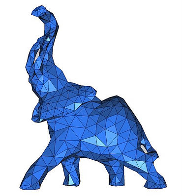
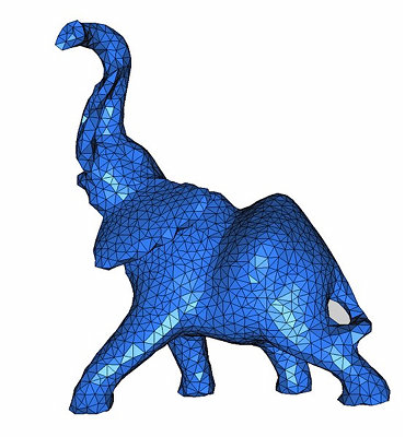
Figure 49.4: View of 3D meshes produced from a polyhedral domain. (i) is a view of file out_1.mesh and (ii) is a view of file out_2.mesh. Code from subsection 49.3.2 generates these files.
49.3.3 Mesh Generation From a Segmented 3D Image
The following code produces a 3D mesh from a 3D image. The image is a segmented medical image in which each voxel is associated a label in accordance with the tissue the voxel belongs to. The domain is therefore a multi-domain where each subdomain corresponds to a specific tissue. The resulting mesh is shown in Figure 49.5.
File: examples/Mesh_3/mesh_3D_image.cpp
#include <CGAL/Exact_predicates_inexact_constructions_kernel.h>

#include <CGAL/Mesh_triangulation_3.h>
#include <CGAL/Mesh_complex_3_in_triangulation_3.h>
#include <CGAL/Mesh_criteria_3.h>

#include <CGAL/Labeled_image_mesh_domain_3.h>
#include <CGAL/make_mesh_3.h>
#include <CGAL/Image_3.h>

// Domain
struct K: public CGAL::Exact_predicates_inexact_constructions_kernel {};
typedef CGAL::Labeled_image_mesh_domain_3<CGAL::Image_3,K> Mesh_domain;

// Triangulation
typedef CGAL::Mesh_triangulation_3<Mesh_domain>::type Tr;
typedef CGAL::Mesh_complex_3_in_triangulation_3<Tr> C3t3;

// Criteria
typedef CGAL::Mesh_criteria_3<Tr> Mesh_criteria;

// To avoid verbose function and named parameters call
using namespace CGAL::parameters;

int main()
{
  // Loads image
  CGAL::Image_3 image;
  image.read("data/liver.inr.gz");

  // Domain
  Mesh_domain domain(image);

  // Mesh criteria
  Mesh_criteria criteria(facet_angle=30, facet_size=6, facet_distance=4,
                         cell_radius_edge=3, cell_size=8);

  // Meshing
  C3t3 c3t3 = CGAL::make_mesh_3<C3t3>(domain, criteria);

  // Output
  std::ofstream medit_file("out.mesh");
  c3t3.output_to_medit(medit_file);

  return 0;
}
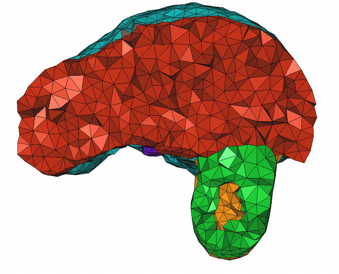
Figure 49.5: Cut-view of a 3D mesh produced from a segmented liver image. Code from subsection 49.3.3 generates this file.
49.3.4 Tuning mesh optimization
In the previous examples, the mesh generation is launched through a call make_mesh_3(domain,criteria) with a minimal number of parameters. In such cases, the default optimization strategy is applied: after the Delaunay refinement process two optimization steps are performed, a perturbation and a sliver exudation. The following examples show how to disable default optimization steps and how to tune the parameters of optimization steps.
Disabling exudation and tuning perturbation
In this first example, we show how to disable the exudation step. The optimization phase after the refinement includes only a perturbation phase which is launched with no time bound and an objective of 10 degrees for the minimum dihedral angle of the mesh. The example shows two ways of achieving the same result. The first way issues a single call to make_mesh_3 with the required optimization process activated and tuned. In the second way, make_mesh_3 is first called without any optimization process and the resulting mesh is next optimized through a call to perturb_mesh_3 with tuned parameters.
File: examples/Mesh_3/mesh_optimization_example.cpp
#include <CGAL/Exact_predicates_inexact_constructions_kernel.h>

#include <CGAL/Mesh_triangulation_3.h>
#include <CGAL/Mesh_complex_3_in_triangulation_3.h>
#include <CGAL/Mesh_criteria_3.h>

#include <CGAL/Labeled_image_mesh_domain_3.h>
#include <CGAL/make_mesh_3.h>
#include <CGAL/Image_3.h>

// Domain
struct K: public CGAL::Exact_predicates_inexact_constructions_kernel {};
typedef CGAL::Labeled_image_mesh_domain_3<CGAL::Image_3,K> Mesh_domain;

// Triangulation
typedef CGAL::Mesh_triangulation_3<Mesh_domain>::type Tr;
typedef CGAL::Mesh_complex_3_in_triangulation_3<Tr> C3t3;

// Mesh Criteria
typedef CGAL::Mesh_criteria_3<Tr> Mesh_criteria;

// To avoid verbose function and named parameters call
using namespace CGAL::parameters;

int main()
{
  // Domain
  CGAL::Image_3 image;
  image.read("data/liver.inr.gz");
  Mesh_domain domain(image);

  // Mesh criteria
  Mesh_criteria criteria(facet_angle=30, facet_size=5, facet_distance=1.5,
                         cell_radius_edge=2, cell_size=7);

  // Mesh generation and optimization in one call
  C3t3 c3t3 = CGAL::make_mesh_3<C3t3>(domain, criteria,
                                      no_exude(),
                                      perturb(sliver_bound=10, time_limit=15));

  // Mesh generation and optimization in several call
  C3t3 c3t3_bis = CGAL::make_mesh_3<C3t3>(domain, criteria,
                                          no_perturb(), no_exude());

  CGAL::perturb_mesh_3(c3t3_bis, domain, time_limit=15, sliver_bound=10);

  // Output
  std::ofstream medit_file("out.mesh");
  c3t3.output_to_medit(medit_file);

  std::ofstream medit_file_bis("out_bis.mesh");
  c3t3_bis.output_to_medit(medit_file_bis);

  return 0;
}
Using Lloyd global optimization
In this second example, we show how to call the Lloyd optimization on the mesh, followed by a call to exudation. We set a time bound of 30s for the Lloyd optimization. We set a time bound of 10s for the exuder and a sliver bound of 10 degrees.
File: examples/Mesh_3/mesh_optimization_lloyd_example.cpp
#include <CGAL/Exact_predicates_inexact_constructions_kernel.h>

#include <CGAL/Mesh_triangulation_3.h>
#include <CGAL/Mesh_complex_3_in_triangulation_3.h>
#include <CGAL/Mesh_criteria_3.h>

#include <CGAL/Labeled_image_mesh_domain_3.h>
#include <CGAL/make_mesh_3.h>
#include <CGAL/Image_3.h>

// Domain
struct K: public CGAL::Exact_predicates_inexact_constructions_kernel {};
typedef CGAL::Labeled_image_mesh_domain_3<CGAL::Image_3,K> Mesh_domain;

// Triangulation
typedef CGAL::Mesh_triangulation_3<Mesh_domain>::type Tr;
typedef CGAL::Mesh_complex_3_in_triangulation_3<Tr> C3t3;

// Mesh Criteria
typedef CGAL::Mesh_criteria_3<Tr> Mesh_criteria;

// To avoid verbose function and named parameters call
using namespace CGAL::parameters;

int main()
{
  // Domain
  CGAL::Image_3 image;
  image.read("data/liver.inr.gz");
  Mesh_domain domain(image);

  // Mesh criteria
  Mesh_criteria criteria(facet_angle=30, facet_distance=1.2,
                         cell_radius_edge=2);

  // Mesh generation and optimization in one call
  C3t3 c3t3 = CGAL::make_mesh_3<C3t3>(domain, criteria,
                                      lloyd(time_limit=30),
                                      no_perturb(),
                                      exude(time_limit=10, sliver_bound=10));

  // Mesh generation and optimization in several call
  C3t3 c3t3_bis = CGAL::make_mesh_3<C3t3>(domain, criteria,
                                          no_perturb(), no_exude());

  CGAL::lloyd_optimize_mesh_3(c3t3_bis, domain, time_limit=30);
  CGAL::exude_mesh_3(c3t3_bis, sliver_bound=10, time_limit=10);

  // Output
  std::ofstream medit_file("out.mesh");
  c3t3.output_to_medit(medit_file);

  std::ofstream medit_file_bis("out_bis.mesh");
  c3t3_bis.output_to_medit(medit_file_bis);

  return 0;
}
49.4 Performances
We provide some performance numbers about our mesh generation engine. The machine used is a PC running Linux64 with two Intel Xeon CPU X5450 clocked at 3.00 GHz with 32GB of RAM. The program has been compiled with g++ v4.3.2 with the -O3 option. Note that our implementation does not take advantage of multi-core architectures.
49.4.1 Delaunay refinement
We study the refinement part of the mesh generation engine in this section. We give CPU time (measured by CGAL::Timer) using the 3 provided oracles. In all experiments, we produce well shaped elements: we set facet angle bound and radius edge bound to their theoretical limit (resp. 30 degrees and 2). We also use the same size for facets and cells.
Implicit function
We mesh an analytical sphere of radius 1.
| Size bound | vertices nb | facets nb | tetrahedra nb | CPU Time (s) |
| 0.4 | 358 | 394 | 1,546 | 0.047 |
| 0.2 | 2,306 | 1,524 | 12,100 | 0.295 |
| 0.1 | 16,832 | 6,234 | 97,109 | 2.46 |
| 0.05 | 127,865 | 24,868 | 776,098 | 22.9 |
| 0.025 | 996,256 | 100,404 | 6,204,502 | 204 |
Polyhedral domain
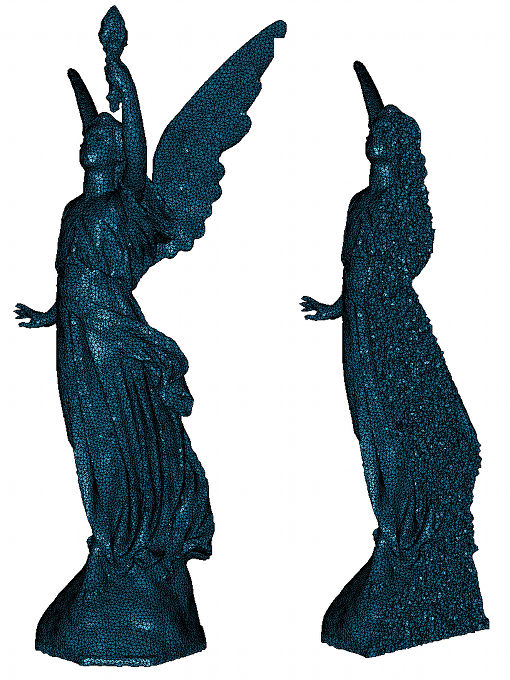
Figure 49.6: View of polyhedral mesh generation result (size = 0.005).
We mesh a volume bounded by a close triangulated surface made of about 50,000 vertices and 100,000 triangles. Picture 49.6 shows the mesh obtained when size is set to 0.005.
| Size bound | vertices nb | facets nb | tetrahedra nb | CPU Time (s) |
| 0.04 | 397 | 674 | 1,262 | 0.339 |
| 0.02 | 2,697 | 3,547 | 11,177 | 2.70 |
| 0.01 | 18,176 | 15,578 | 90,480 | 19.7 |
| 0.005 | 129,377 | 64,793 | 721,355 | 152 |
3D image
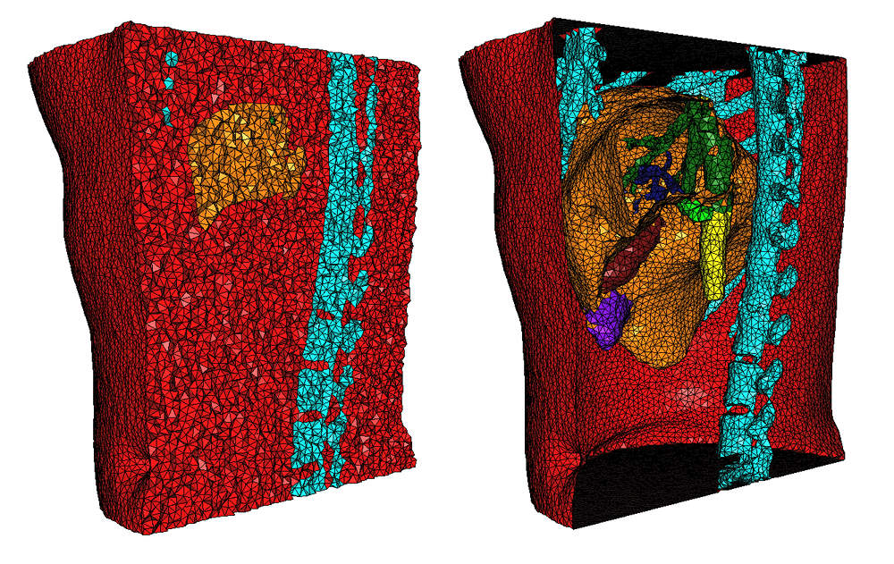
Figure 49.7: View of 3d image mesh generation result (size = 4).
We mesh image number 2 from the 3D-IRCADb-011 public database. The size of this image is 512x512x172 voxels (about 45M voxels). The size of the voxels is 0.78mm x 0.78mm x 1.6mm. Picture 49.7 shows the mesh obtained for size set to 4.
| Size bound (mm) | vertices nb | facets nb | tetrahedra nb | CPU Time (s) |
| 16 | 3,743 | 3,735 | 19,886 | 0.880 |
| 8 | 27,459 | 19,109 | 159,120 | 6.97 |
| 4 | 199,328 | 76,341 | 1,209,720 | 54.1 |
| 2 | 1,533,660 | 311,420 | 9,542,295 | 431 |
49.5 Design and Implementation History
Work on the package Mesh_3 started during the PhD thesis of Laurent Rineau advised by Mariette Yvinec. A first version of the specifications and code came out of their collaboration.
From the beginning of 2009, most of the work has been performed by Stéphane Tayeb, in collaboration with Mariette Yvinec, Laurent Rineau, Pierre Alliez and Jane Tournois. First, Stéphane released the first public version of the package, implementing the specifications written by Laurent and Mariette.
Since then, Stéphane added the optimization processes which are heavily based on the work of Jane Tournois and Pierre Alliez during the PhD of Jane advised by Pierre.
In collaboration with Laurent Rineau, Stéphane also added demos and examples.
Footnotes
| 1 | available at http://www.ircad.fr/softwares/3Dircadb/3Dircadb1/index.php |