

|
CGAL 5.1 - 3D Periodic Mesh Generation
|
|
CGAL 5.1 - 3D Periodic Mesh Generation
|
This package is devoted to the generation of isotropic simplicial meshes discretizing periodic 3D domains. The domain to be meshed is a subset of the three-dimensional flat torus (see Section The Flat Torus of the package 3D Periodic Triangulations). The domain may be connected or composed of multiple components and/or subdivided in several subdomains. The current implementation provides classes to represent domains bounded by isosurfaces of implicit functions defined over a cube.
Boundary and subdivision surfaces are either smooth or piecewise-smooth surfaces, formed with planar or curved surface patches. Surfaces may exhibit 1-dimensional features (e.g. crease edges) and 0-dimensional features (e.g. singular points as corners tips, cusps or darts), that have to be fairly approximated in the mesh.
The output mesh is a periodic 3-dimensional triangulation, including subcomplexes that approximate each input domain feature: subdomain, boundary surface patch or input domain feature with dimension 0 or 1. Thus, the output mesh includes a 3D submesh covering each subdomain, a surface mesh approximating each boundary or subdividing surface patch, a polyline approximation for each 1-dimensional feature and of course a vertex on each corner.
The main entry points of the package are two global functions that respectively generate and refine such meshes. The mesh generator is customized to output a mesh that fits as much as possible the user needs, for instance in terms of sizing field or with respect to some user customized quality criteria.
The meshing engine used in this mesh generator is based on Delaunay refinement [4], [7], [8]. It uses the notion of restricted Delaunay triangulation to approximate 1-dimensional curves and surface patches [1]. Before the refinement, a mechanism of protecting balls is set up on 1-dimensional features, if any, to ensure a fair representation of those features in the mesh, and also to guarantee the termination of the refinement process, whatever may be the input geometry, in particular whatever small angles the boundary and subdivision surface patches may form [2], [3]. The Delaunay refinement is followed by a mesh optimization phase to remove slivers and provide a good quality mesh.
This package is fundamentally linked to the package 3D Mesh Generation, which is devoted to the generation of isotropic simplicial meshes discretizing (non-periodic) 3D domains and to the 3D Periodic Triangulations of CGAL, which are used as underlying triangulation structures of the mesh.
A periodic mesh extends, by definition, infinitely in space. We consider the flat torus \( \mathbb T_c^3\), whose canonical cube has side length c (this canonical cube is named original domain in Chapter 3D Periodic Triangulations; we rename it here to avoid the confusion with the domain defined in Chapter 3D Mesh Generation). Well-chosen "dummy" points are inserted at the beginning of the meshing process, ensuring that the projection of the periodic triangulation into the flat torus \( \mathbb T_c^3\) forms at all times a simplicial complex (see Sections The Flat Torus and Representation of the manual of 3D periodic triangulations). Thanks to this construction, the meshing process can be exclusively conducted within the canonical cube. The mesh can then be created using the 3D Mesh Generation package of CGAL. As this package originally aims to mesh non-periodic domains of \( \mathbb R^3\), an interface is necessary between the packages 3D Mesh Generation and 3D Periodic Triangulations. This package provides this interface.
The domain to be meshed is assumed to be representable as a pure 3D complex. A 3D complex is a set of faces with dimension 0, 1, 2, and 3 such that all faces are pairwise interior disjoint, and the boundary of each face of the complex is the union of lower-dimensional faces of the complex. The 3D complex is pure, meaning that each face is included in a face of dimension 3, so that the complex is entirely described by the set of its 3D faces and their subfaces. However the 3D complex needs not be connected. The set of faces with dimension lower or equal than 2 forms a 2D subcomplex which needs not be manifold, neither pure, nor connected: some 3D faces may have dangling 2D or 1D faces in their boundary faces.
In the rest of the documentation, we will refer to the input 3D complex as the input domain. The faces of the input domain with dimension 0, 1, 2, and 3 are called respectively corners, curves, surface patches, and subdomains to clearly distinguish them from the faces of the mesh that are called vertices, edges, facets and cells.
Note that the input complex faces are not required to be linear nor smooth. Surface patches, for instance, may be smooth surface patches, or portions of surface meshes with boundaries. Curves may be for instance straight segments, parameterized curves, or polylines. Each of those features will be accurately represented in the final mesh.
The 0 and 1-dimensional features of the input domain are usually singular points of the subdomain boundaries, however this is not required. Furthermore, those features are not required to cover all the subdomains boundaries singularities but only those that need to be accurately represented in the final mesh. In the following, we say that a domain has features when it has 0 and 1-dimensional features that need to be accurately represented in the mesh, and we call those features exposed features. Therefore, a domain may be without features either because all boundary surface patches are smooth closed surfaces, or simply because the curves joining different surface patches and the singularities of those patches need not be accurately approximated in the final mesh.
Note also that input complex faces are not required to be connected. Faces of the input domain are identified by indices. If a subdomain is not connected, its different components receive the same index. Likewise different surface patches, segment curves, or corners may share the same index. Each connected component of a feature will be accurately represented in the final mesh. Note however that the occurrence of multiply connected faces in the input complex may affect the relevance of internal topological checks performed by the mesh generator.
The domain is passed to the mesh generation function as a domain class, often called the oracle, that provides predicates and constructors related to the domain, the subdomains, and the boundary surface patches. Mainly, the oracle provides a predicate to test if a given query point belongs to the domain or not and to find in which subdomain it lies in the affirmative case. The domain class also provides predicates and constructors to test the intersection of a query line segment with the boundary surface patches and to construct intersection points, if any.
An implicit domain is a domain described by an implicit function. The bounding surface is described implicitly as the zero level set of a function defined over the three dimensional flat torus. The domain to be discretized is assumed to be the domain where the function has negative values.
As described in Section Relation to the 3D Mesh Generation and 3D Periodic Triangulations Packages, the periodic mesh is in fact constructed over a single cube of side c in \( \mathbb R^3\), the canonical cube of the flat torus \( \mathbb T_c^3\). The origin (given by three coordinates \( \alpha\), \( \beta\), and \( \gamma\)) of this cube and the period c are input parameters chosen by the user. The cube \( [\alpha,\alpha+c)\times[\beta,\beta+c)\times[\gamma,\gamma+c)\) contains exactly one representative of each element in \( \mathbb T_c^3\). Although the mesh is only constructed over the canonical cube, some of the oracles used during the generation of the mesh must sometimes be evaluated outside of the canonical cube. The implicit function describing the domain to be meshed must thus be defined over the whole Euclidean space and be periodic, with a period compatible with the canonical cube.
The specifications of the input implicit function described in the previous section are quite restrictive. To relax these requirements, this package also offers a wrapper class, CGAL::Periodic_3_function_wrapper, to artificially construct periodic functions compatible with the user-defined canonical cube, from the values of an implicit function over the canonical cube. It is thus possible to construct periodic domains described by implicit functions that are not intrinsically periodic, for example a sphere (see Figure 59.4) or a cone (see Section Example of a Cone-like Periodic Domain).
The resulting mesh is output as a subcomplex of a weighted Delaunay periodic 3D triangulation, in a class that provides various iterators on mesh elements.
This periodic 3D triangulation provides approximations of the subdomains, surface patches, curves, and corners according to the restricted Delaunay triangulation paradigm. This means that each subdomain is approximated by the union of the tetrahedral cells whose circumcenters are located inside the domain (or subdomain). Each surface patch is approximated by the union of the Delaunay mesh facets whose dual Voronoi edges intersect the surface patch. Such mesh facets are called surface facets in the following. The 1-dimensional exposed features are approximated by sequences of mesh edges and the 0-dimensional exposed features are represented by mesh vertices.
It is possible to extract the facets of the complex (restricted to the canonical cube) as a FaceGraph, using the function facets_in_complex_3_to_triangle_mesh().
The mesh generation algorithm is mainly a Delaunay refinement process. This Delaunay refinement process is driven by criteria concerning either the size and shape of mesh cells and surface facets. The refinement process terminates when there are no more mesh cells or surface facets violating the criteria.
The criteria are designed to achieve a nice spread of the mesh vertices while ensuring the termination of the refinement process. Those criteria may be somehow tuned to the user needs to achieve for instance the respect of a sizing field by mesh elements, some topological conditions on the representation of boundary surfaces in the mesh, and/or some error bound for the approximation of boundary surfaces. To some extent, the user may tune the Delaunay refinement to a prescribed trade-off between mesh quality and mesh density. The mesh density refers to the number of mesh vertices and cells, i.e. to the complexity of the mesh. The mesh quality referred to here is measured by the radius edge ratio of surface facets end mesh cells, where the radius edge ratio of a simplex (triangle or tetrahedron) is the ratio between its circumradius and its shortest edge length.
If the domain description includes 0 dimensional features, the corresponding points are inserted into the Delaunay triangulation from the start.
If the domain has 1-dimensional exposed features, the method of protecting balls [2], [3] is used to achieve an accurate representation of those features in the mesh and to guarantee that the refinement process terminates whatever may be the dihedral angles formed by input surface patches incident to a given 1-feature or the angles formed by two 1-features incident to a 0-feature. See Section Protection of 0 and 1-dimensional Exposed Features in the documentation of the package 3D Mesh Generation for further information.
Section Meshing Domains with Sharp Features details how to prescribe sharp features and examples of periodic meshes with features.
The optimization phase is a succession of optimization processes which aim to improve the quality of the mesh in terms of shape of its elements. All the optimizers offered by the package 3D Mesh Generation are also available for periodic mesh generation:
See Sections Optimization Phase, The Optimization Parameters, and Tuning Mesh Optimization in the documentation of the package 3D Mesh Generation for further information.
A periodic 3D mesh generation process is launched through a call to one of the two following functions:
The function make_periodic_3_mesh_3() generates from scratch a periodic mesh of the input domain, while the function refine_periodic_3_mesh_3() refines an existing periodic mesh of the input domain.
refine_periodic_3_mesh_3(). The underlying triangulation of a mesh complex obtained through make_periodic_3_mesh_3() or refine_periodic_3_mesh_3() will always satisfy this condition.The following sections describe the different template parameters (and their requirements) of these two global functions.
The template parameter C3T3 is required to be a model of the concept MeshComplex_3InTriangulation_3. This data structure is devised to represent a three-dimensional complex embedded in a periodic 3D triangulation. In both functions, an instance of type C3T3 is used to maintain the current approximating simplicial mesh and to represent a single copy of the final periodic 3D mesh at the end of the procedure.
The embedding periodic 3D triangulation is required to be the nested type CGAL::Periodic_3_mesh_triangulation_3::type, provided by the class template CGAL::Periodic_3_mesh_triangulation_3. The type for this triangulation is a wrapper around the class CGAL::Periodic_3_regular_triangulation_3 whose vertex and cell base classes are respectively models of the concepts MeshVertexBase_3 and MeshCellBase_3.
The template parameter PeriodicMeshDomain is required to be a model of the concept Periodic_3MeshDomain_3. The argument domain of type PeriodicMeshDomain is the sole link through which the periodic domain to be discretized is known by the mesh generation algorithm.
This concept provides, among others, member functions to test whether or not a query segment intersects boundary surfaces, and to compute an intersection point in the affirmative. The Periodic_3MeshDomain_3 concept adds member functions which given a query point tell whether the point lies inside or outside the domain and in which subdomain the point lies, if inside.
If the domain description includes 0 and 1-dimensional features that have to be accurately represented in the final mesh, the template parameter PeriodicMeshDomain is required to be of a model of the concept Periodic_3MeshDomainWithFeatures_3, which mainly provides the incidence graph of 0, 1 and 2-dimensional features, and a member function to construct sample points on curves.
Users whose domain is a model of Periodic_3MeshDomainWithFeatures_3 can choose to have the corners and curves of the domain represented in the mesh or not, using the following parameters:
parameters::features() sets features according to the domain, i.e. 0 and 1-dimensional features are taken into account if domain is a MeshDomainWithFeatures_3. parameters::no_features() prevents the representation of 0 and 1-dimensional features in the mesh. This is useful to get a smooth and rough approximation of a domain with features. The template parameter MeshCriteria must be a model of the concept MeshCriteria_3, or a model of the refined concept MeshCriteriaWithFeatures_3 if the domain has exposed features. The argument of type MeshCriteria passed to the mesh generator specifies the size and shape requirements for the tetrahedra in the mesh and for the triangles in the boundary surface mesh. These criteria condition the rules that drive the refinement process. At the end of the refinement process, mesh elements satisfy the criteria. This may not be strictly true anymore after the optimization phase, but this last phase is devised to only improve the mesh quality.
The periodic mesher makes use of the same criteria as the non-periodic meshing functions. This is made possible because criteria use methods directly from the underlying triangulation, to know the smallest edge length of a triangle, for example. The periodicity is therefore taken into account at this level and no modification of the criteria classes are required.
The criteria for surface facets are governed by the four following parameters:
facet_angle. This parameter controls the shape of surface facets. Specifically, it is a lower bound for the angle (in degree) of surface facets. When boundary surfaces are smooth, the termination of the meshing process is guaranteed if this angular bound is at most 30 degrees [4]. facet_size. This parameter controls the size of surface facets. Each surface facet has a surface Delaunay ball which is a ball circumscribing the surface facet and centered on the surface patch. The parameter facet_size is either a constant or a spatially variable scalar field, providing an upper bound for the radii of surface Delaunay balls. facet_distance. This parameter controls the approximation error of boundary and subdivision surfaces. Specifically, it is either a constant or a spatially variable scalar field. It provides an upper bound for the distance between the circumcenter of a surface facet and the center of a surface Delaunay ball of this facet. facet_topology. This parameters controls the set of topological constraints which have to be verified by each surface facet. By default, each vertex of a surface facet has to be located on a surface patch, on a curve, or on a corner. It can also be set to check whether the three vertices of a surface facet belongs to the same surface patch. This has to be done cautiously, as such a criterion needs that each intersection of input surface patches is an input 1-dimensional feature. The criteria for mesh cells are governed by two parameters:
cell_radius_edge_ratio. This parameter controls the shape of mesh cells (but can't filter slivers, as we discussed earlier). It is an upper bound for the ratio between the circumradius of a mesh tetrahedron and its shortest edge. There is a theoretical bound for this parameter: the Delaunay refinement process is guaranteed to terminate for values of cell_radius_edge_ratio bigger than 2. cell_size. This parameter controls the size of mesh tetrahedra. It is either a scalar or a spatially variable scalar field. It provides an upper bound on the circumradii of the mesh tetrahedra. If the domain has 1-dimensional exposed features, the criteria includes a sizing field to guide the sampling of 1-dimensional features with protecting balls centers.
edge_size. This constant or variable scalar field is used as an upper bound for the distance between two protecting ball centers that are consecutive on a 1-feature. This parameter has to be set to a positive value when 1-dimensional features protection is used. This section presents various use cases of the periodic mesh generator.
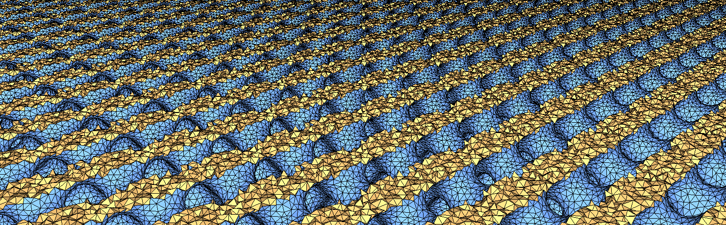
Generated meshes can be output to the .mesh file format, which can be visualized with the demo of the package 3D Polyhedral Surface. The function CGAL::output_periodic_mesh_to_medit() takes a stream, a mesh complex, and - optionally - the number of periodic copies that should be drawn, making it easier to observe the periodicity of the result. Figure 59.2 illustrates the different output for the three possible number of copies: 1, 4, and 8.
In the following examples (except on Figure 59.6), each copy of a periodic mesh will be attributed a unique color.
The following code produces a 3D periodic mesh for a domain whose boundary surface is an isosurface defined by an implicit function. Note the use of named parameters (from the Boost library) in the constructor of the Mesh_criteria instance. Figure 59.3 shows the resulting mesh.
File Periodic_3_mesh_3/mesh_implicit_shape.cpp
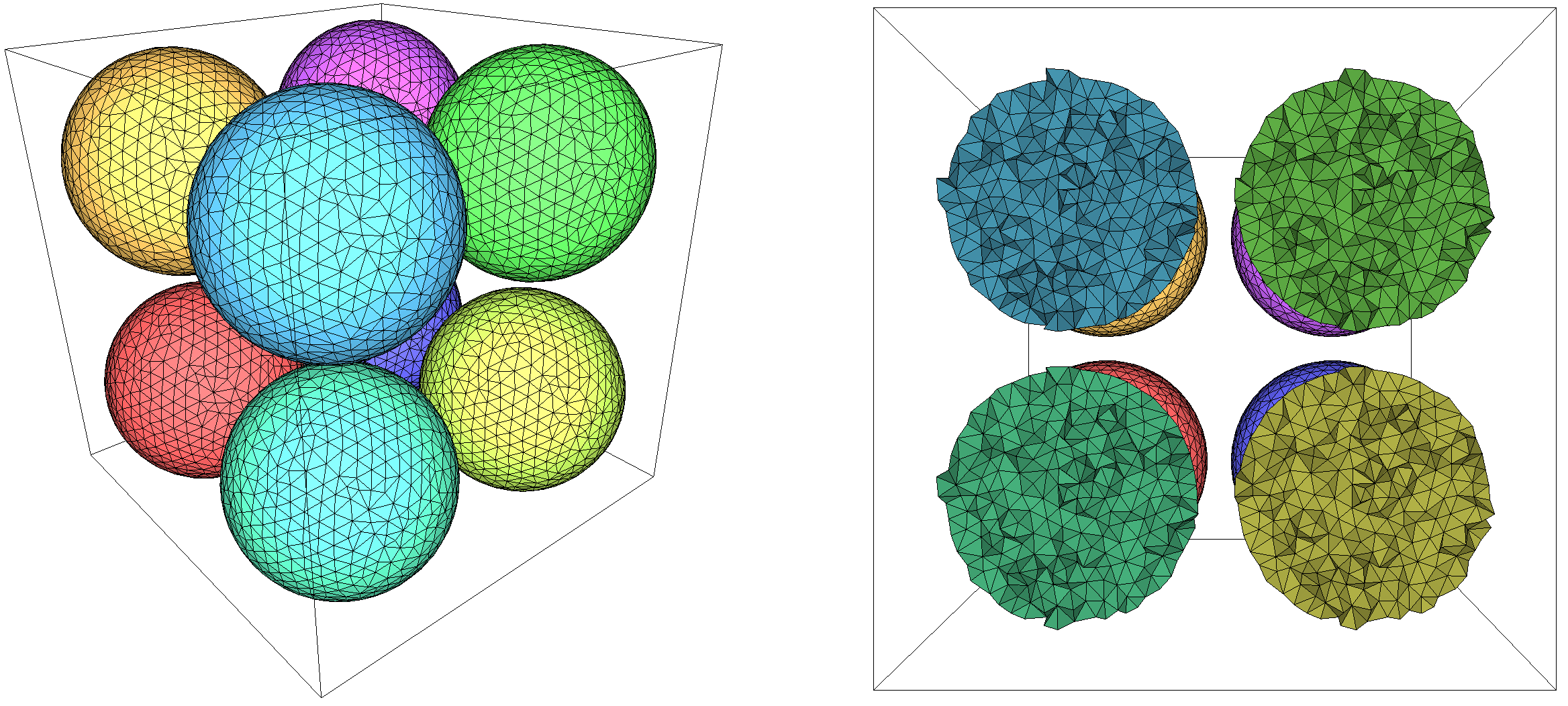
While the implicit function used in the previous example is defined and periodic over the complete space, it is also possible to consider non-periodic implicit functions defined entirely within the canonical cube (or over the whole space) by using the wrapper class CGAL::Periodic_3_function_wrapper. Values will then be periodically duplicated, creating a periodic function. For example, replacing the previous domain with the following non-periodic implicit function (a sphere):
will yield the mesh shown on Figure 59.4.
In the case of periodic mesh generation, the exterior of an isosurface defined by an implicit function can also be meshed because it is a finite space. The class Implicit_to_labeled_subdomains_function_wrapper is a convenient wrapper to achieve this by internally transforming the interior and the exterior as simply two subdomains to be meshed. Compared to the previous example, it can be simply achieved by adding the line
and wrapping the function as follows:
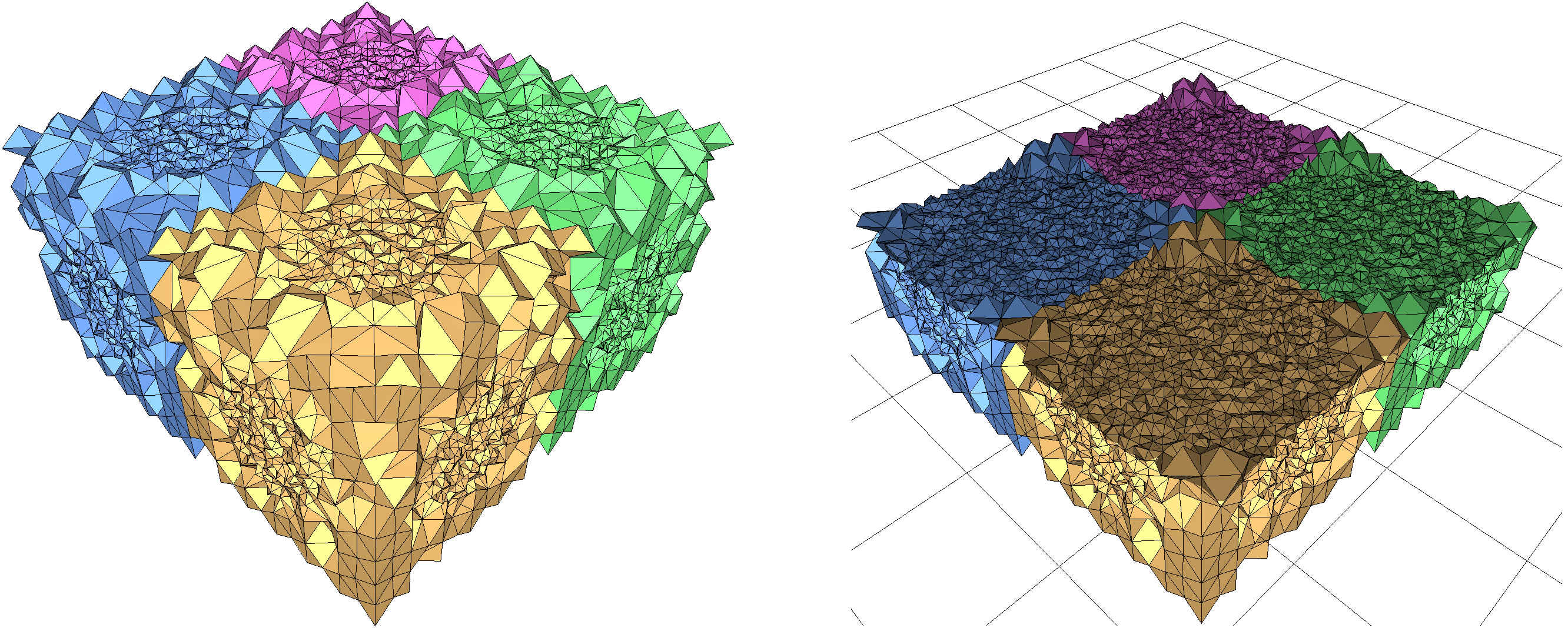
Figure 59.5 shows the periodic mesh obtained after this change. Note that both subdomains are meshed with different cell sizing fields, which can be obtained using the class Mesh_constant_domain_field_3. See Example mesh_implicit_shape_with_subdomains.cpp for the complete code.
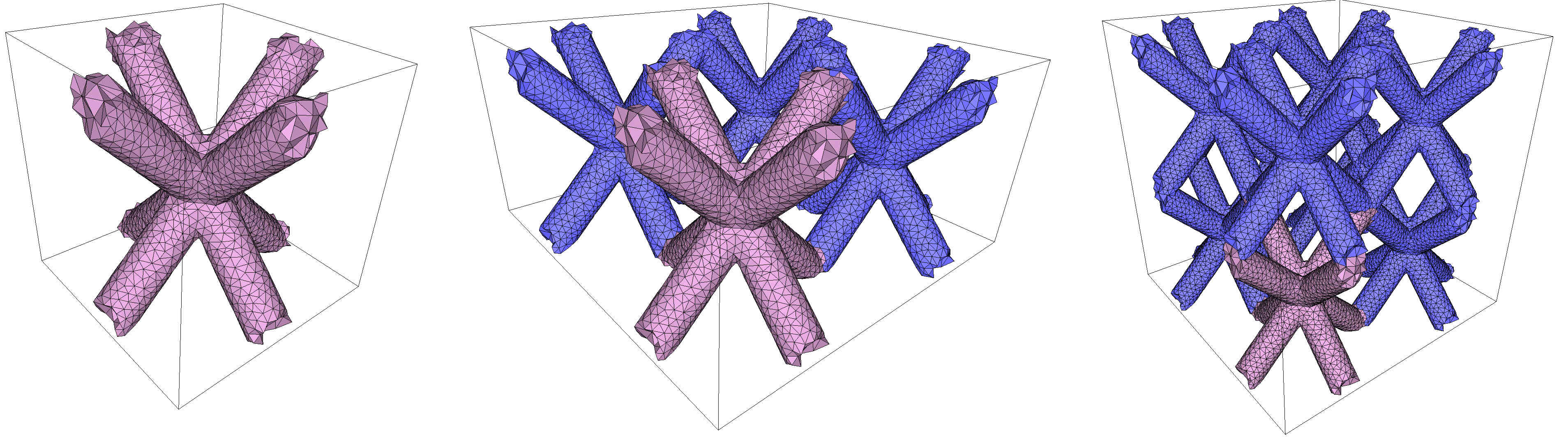
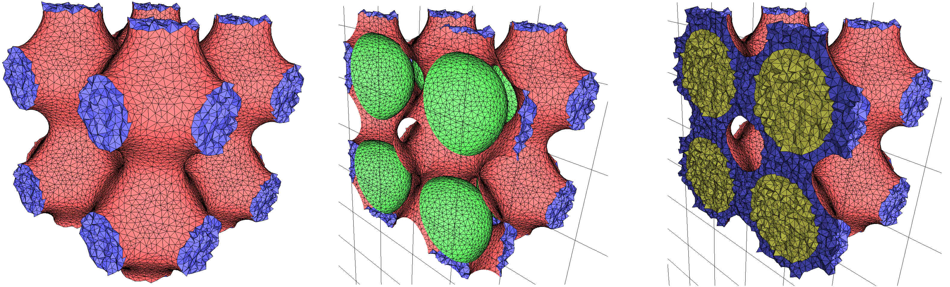
The following code produces a 3D periodic mesh for a domain consisting of a combination of the two implicit functions used in the previous example: a sphere is encompassed within the implicit domain of Figure 59.3. The class Implicit_multi_domain_to_labeling_function_wrapper is used as model of ImplicitFunction, required by the class Labeled_mesh_domain_3. The set of subdomains is given by a vector of vector of signs. Each subdomain corresponds to a sign vector [s1, s2, ..., sn], where si is the sign of the function fi(p) at a point p of the subdomain. Figure 59.6 shows a view and a cut view of the resulting mesh.
File Periodic_3_mesh_3/mesh_implicit_multi_domain.cpp
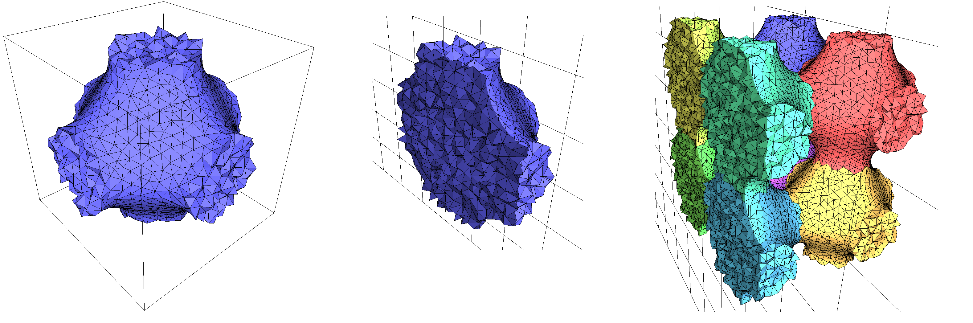
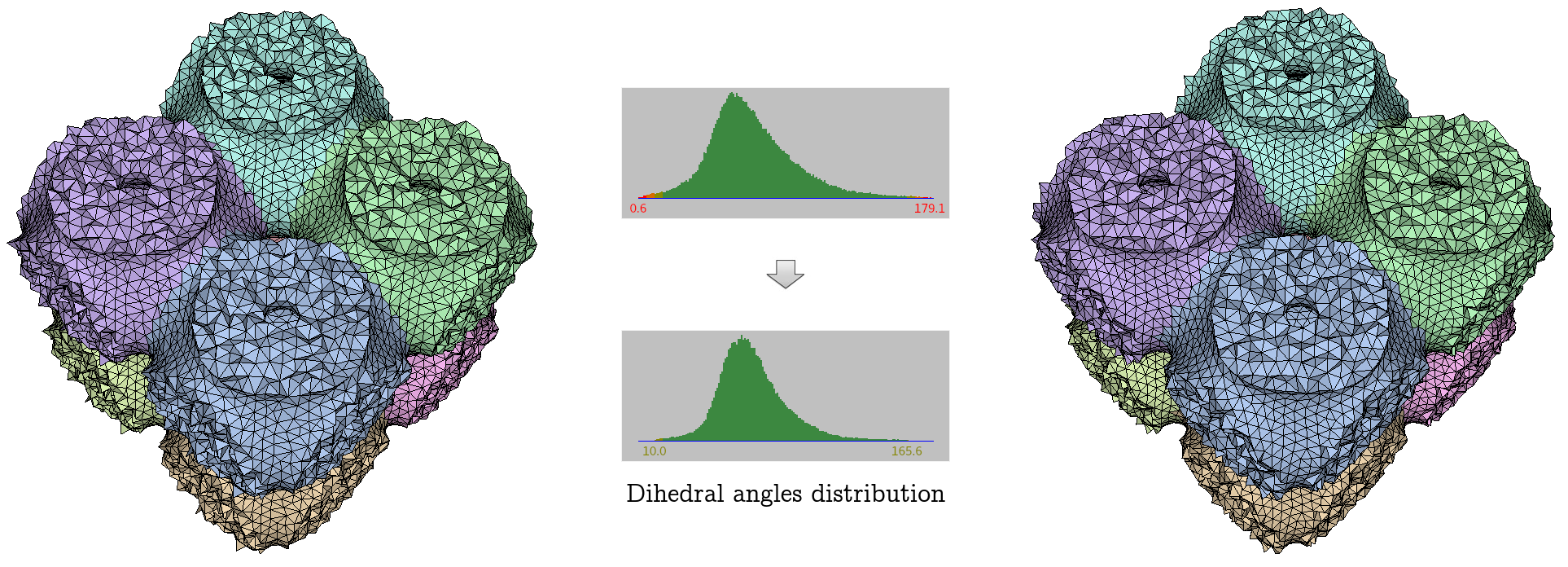
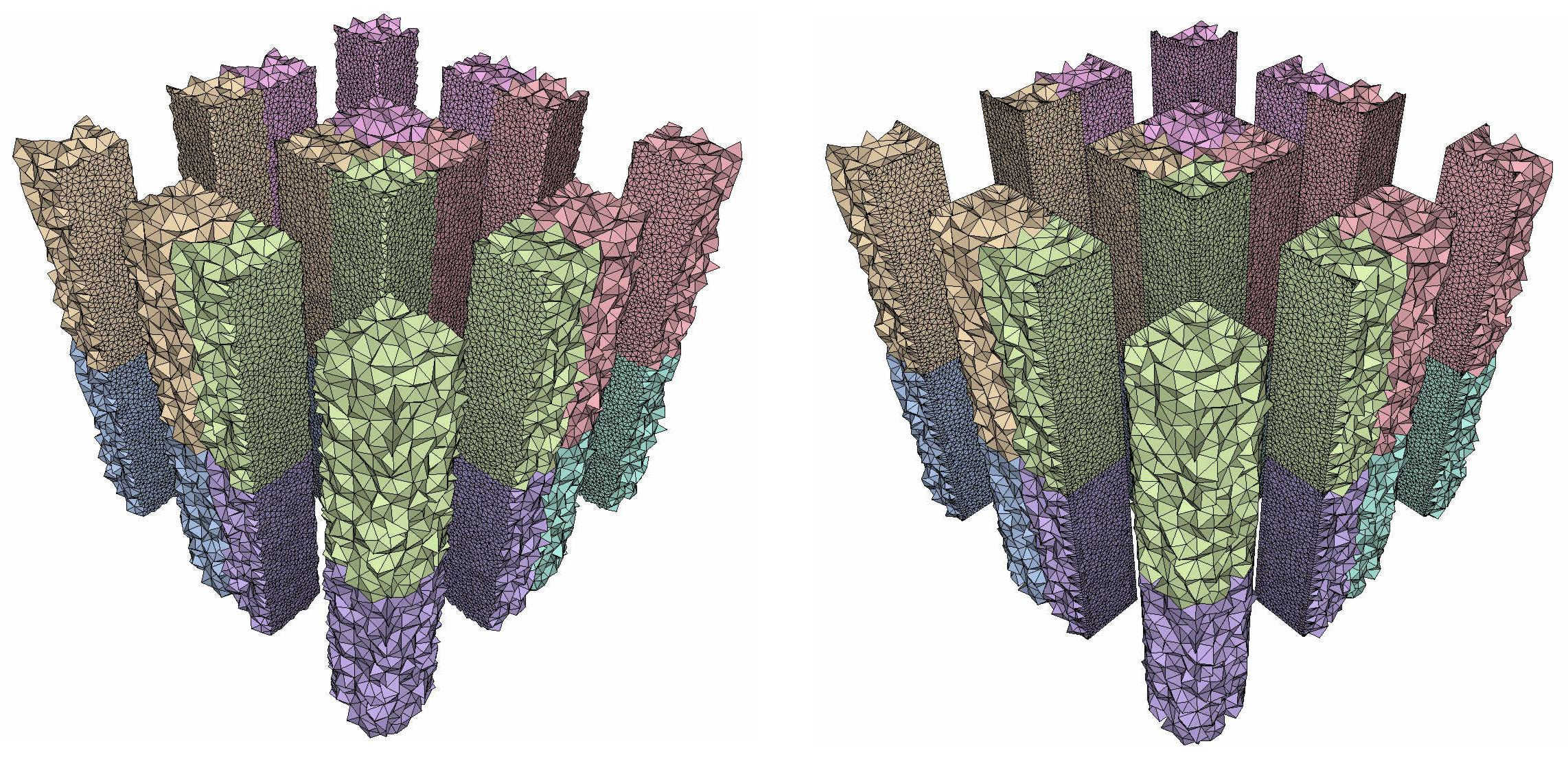
In the previous examples, the mesh generation is launched through a call make_periodic_3_mesh_3() with a minimal number of parameters. In such cases, the default optimization strategy is applied: after the Delaunay refinement process two optimization steps are performed, a perturbation and a sliver exudation. The following example shows how to enable and disable the various optimization methods. Figure 59.6 shows the resulting periodic mesh before and after optimizations.
File Periodic_3_mesh_3/mesh_implicit_shape_with_optimizers.cpp
The periodic mesh generator currently operates on domains described by one or multiple implicit functions. Sharp features to be preserved must then be explicitly specified by hand by the user, using the mesh domain class CGAL::Mesh_domain_with_polyline_features_3 and its functions add_corners() and add_features(). These functions allow to specify curves (as a polyline – a list of points with two consecutive points forming a segment of the curve) and corners which should appear in the final mesh. Note that the discretization of the specified curves might change: for example, a curve might be subdivided in smaller segments or simplified in larger segments, but the prescribed geometry will still be present in the final mesh.
To ensure the good protection of features, some requirements are put on the curves and corners that are specified by the user:
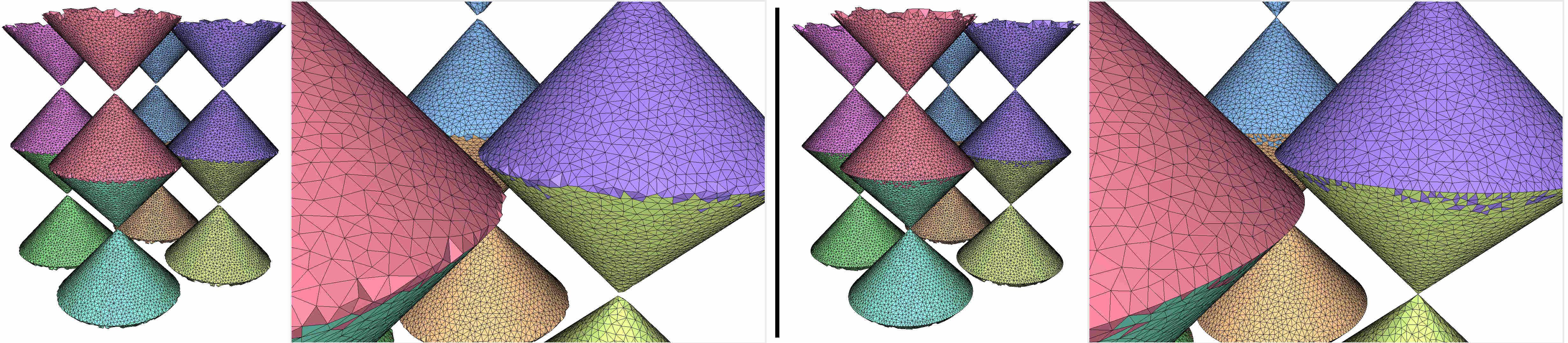
cycle).(2,2,2)--(3,3,3) as feature and the point (1.5, 1.5, 1.5) as corner: once the periodicity is taken in account, the point is actually the middle of the segment.The example below uses two different types of protecting features: a cycle to protect the base of the cone, and a corner at the apex of a cone, which ensures that the apex will appear in the mesh. Figure 59.8 shows the comparison between the same domain meshed with the same criteria when protection is disabled and enabled.
Note the use of a more complex intrinsically non-periodic implicit function as input domain.
File Periodic_3_mesh_3/mesh_implicit_shape_with_features.cpp
It is possible to prescribe features that will, due to periodicity, form a continuous polyline that extends infinitely in space. A simple example of such occurrence is the segment (0,0,0) -- (1,1,1) when considering the unit cube as canonical cube. Figure 59.8 shows an implicit function describing a square-based prism such that the axis of the prism is the (Oz) axis. (The prism is thus 'cut' into 4 pieces when considered within a single copy of the periodic space.) The canonical cube is the unit cube and the following polylines have been specified to protect edges:
Advanced use cases of the 3D mesh generator with implicit domains, its optimizers, and protection mechanisms can be found in Section Examples of the package 3D Mesh Generation.
Theoretical foundations of periodic meshes are explained in detail in the package 3D Periodic Triangulations. For the theoretical foundations of the mesh generation process, see Section Theoretical Foundations of the package 3D Mesh Generation.
The work on this package started during the PhD thesis of Mikhail Bogdanov, advised by Monique Teillaud, which resulted in a first prototype.
From the beginning of 2014, most of the work was performed by Aymeric Pellé, in collaboration with Monique Teillaud. Their collaboration produced a first set of design and specifications [6].
This initial implementation was enhanced by Mael Rouxel-Labbé in 2017, in collaboration with Monique Teillaud, to provide a more robust implementation, integrate optimizations, handle 0- and 1-dimensional features, and publish the first version of this package.
 1.8.13