CGAL 6.0 - Kinetic Surface Reconstruction
Loading...
Searching...
No Matches
User Manual

Authors
Sven Oesau and Florent Lafarge

Introduction

Reconstruction of man-made objects from point clouds pose a challenge to traditional surface reconstruction methods that often produce a smooth surface, e.g., by meshing a fitted implicit function, see Poisson Surface Reconstruction, or by interpolation, see Advancing Front Surface Reconstruction and Scale Space Surface Reconstruction. The kinetic surface reconstruction package implements the pipeline proposed by Bauchet et. al [1]. At the core is the Kinetic space partition which efficiently decomposes the bounding box into a set of convex polyhedra. The decomposition is guided by a set of planar shapes which are aforehand abstracted from an input point cloud. The final surface is obtained via an energy formulation trading data faithfulness for low complexity which is solved via min-cut. The output is a polygonal watertight mesh.

The method overcomes the major limitation of similar approaches which decompose the bounding box using planar shapes. By partitioning the space into fewer cells using the kinetic approach and aforehand splitting of input data via an adaptive octree the method beats the common full decomposition of the bounding box which has a complexity of \(O(n^3)\). This allows for effective handling of large scenes. At the same time the kinetic approach of decomposing the bounding box limits the number of tiny cells in the partition. Tiny cells are often responsible for small artifacts and at the same time increase the memory requirements and running time.

Algorithm

The method takes as input a point cloud with oriented normals, see Figure 69.1. In a first step, Shape Detection is used to abstract planar shapes from the point cloud. The optional regularization of shapes, see Shape regularization, can not just improve the accuracy of the data by aligning parallel, coplanar and orthogonal shapes, but provides in the same time a reduction in complexity. Before inserting the planar shapes into the kinetic space partition, coplanar shapes are merged into a single shape and the 2d convex hull of each shape is constructed. The reconstruction is posed as an energy minimization labeling the convex volumes of the kinetic space partition as inside or outside. The optimal surface separating the differently labeled volumes is found via min-cut. A graph is embedded into the kinetic partition representing every volume by a vertex and every face between to volumes by an edge connecting the corresponding vertices.

\(\DeclareMathOperator*{\argmin}{arg\,min} \argmin\limits_{l \in {\{0, 1\}}^n} E(l) = (1 - \lambda) D(l) + \lambda U(l)\)

\(D(l) = \sum\limits_{i \in C}\sum\limits_{p \in I_i}d_i(p, l_i)\)

\(U(l) = \frac{I}{A}\sum\limits_{i\mathtt{\sim} j}a_{ij} \cdot (1-\delta_{l_i,l_j})\)

The energy function trads data term for regularization term via parameter \(\lambda\)

The data term counts votes from the points \(p \in I_i\) based on their associated normal pointing towards or away from each volume \(i \in C\).

The regularization term penalizes the total surface area and thus favors surfaces with low complexity.

The labels \(l \in {\{0, 1\}}^n\) denote the label for the \(n\) volumes of the kinetic space partition. The data term measures the coherence of the labeled volumes with the orientation of normals of the input points. The preferred label for a volume is determined by a voting of the input points and their associated normals. For each volume \(i \in C\) the inliers from the shape detection associated with the faces of the volume \(I_i\) either vote inside or outside for the volume. The vote is inside \(d_i(p, inside) = 1\) and \(d_i(p, outside = 0)\) if the normal associated to the point is directed to the outwards of the volume or outside \(d_i(p, inside) = 0\) and \(d_i(p, outside = 1)\) if the normal is oriented inwards. The regularization term is penalizing the total surface area of the surface and thus favoring less complex surfaces. To put the data term and regularization term into balance, area of each face is normalized by the total area of all faces \(A\) and scaled by twice the total number of inliners \(I\) from the shape detection as each inlier counts as one inside and one outside vote.

Thus the reconstruction is guaranteed to be watertight as it equals a union of volumes. However, the reconstruction may consist of several components and is not guaranteed to be 2-manifold as different components may share a vertex or an edge.

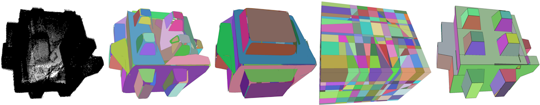
Figure 69.1 Kinetic surface reconstruction pipeline.
From left to right: 1. input point cloud with 382k points 2. 98 detected planar shapes 3. 63 regularized convex shapes 4. kinetic space partition with 1,487 cells 5. reconstructed polygonal mesh with 131 faces.


Parameters

The parameters of the method include the parameters from other packages which are used internally:

  • Shape detection: k_neighbors, maximum_distance, maximum_angle and minimum_region_size
  • Shape Regularization: maximum_offset, angle_tolerance, regularize_parallelism, regularize_coplanarity, regularize_orthogonality, regularize_axis_symmetry and symmetry_direction
    • angle_tolerance is replacing maximum_angle from Shape regularization due to a name collision with Shape detection
  • Kinetic space partition: k, reorient_bbox and bbox_dilation_ratio

The reconstruction adds two new parameters:

  • external_nodes: The min-cut formulation embeds a vertex into each volume and connects all vertices if the corresponding volumes share a common face. While each face inside the kinetic space partition is exactly between two volumes, faces on the boundary do not. Thus, 6 external vertices are inserted into the graph representing a volume on each side of the bounding box. The parameter external_nodes allows the user to either provide a fixed label inside or outside for each node or leave the label up to the energy minimization. Typical choices for this parameter are to choose all external nodes as outside for scanned objects, e.g., as in Figure 69.1, or the ZMIN node inside and all other nodes outside as for exterior scans of buildings, e.g., as in Figure 69.2. The default value for this parameter is to leave the labels of the external nodes up to the energy minimization. The alternative method reconstruct_with_ground estimates a ground plane within the detected shapes and sets up all faces on the bounding box below that ground plane to be connected to an external node set as inside while all other faces on the outside are connected to external nodes set to outside. It assumes the z-axis to be the upward pointing vertical direction.
  • lambda: The lambda parameter trades the data faithfulness of the energy minimization for low complexity. The parameter has to be chosen in the range of \([0,1)\). \(0\) indicates maximal data faithfulness, while the default value of \(0.5\) gives an equal weight to data faithfulness and low complexity. The value should be chosen according to the quality of the input data. If the point cloud is accurate, low in noise and complete a low value can be chosen.

Choice of Parameters

The kinetic space partition determines all possible reconstructions as the energy formulation only decides about the labels for the volumes, but cannot change the volumes themselves. Thus, the first stages of the pipeline, Shape Detection and Shape Regularization, have a large impact on the final reconstruction. In the simple case of a cube, one missing side would depending on the chosen lambda parameter either make the cube expand on that side towards the bounding box or make the full cube disappear. A proper parameterization of the Shape Detection to detect all relevant shapes may have a large impact. The debug parameter allows to export intermediate results for inspection. This is especially helpful for larger scenes, where the time for the whole reconstruction requires more computational effort.

However, in many cases a point cloud may be incomplete and not cover all shapes. The method offers two parameters to handle missing data. The k parameter of the kinetic space partition can extend the convex polygons further in the partition and thus may make up for missing shapes. The external_nodes parameter allows to preset an inside or outside label for bounding box sides. This is especially helpful for scanned buildings, where no points have been collect on the bottom side of the building, partial scans or scans where the orientation is inverted, e.g., inside an apartment.

The lambda parameter allows to trade data faithfulness for low complexity. The best choice depends on the individual point cloud and the sampled object. Figure 69.2 shows the lower complexity of the reconstruction with a higher lambda value. However, the actual reconstruction using min-cut only makes up a small fraction from the whole pipeline. Performing several reconstructions with different values of lambda is a reasonal approach, see Parameters Example.

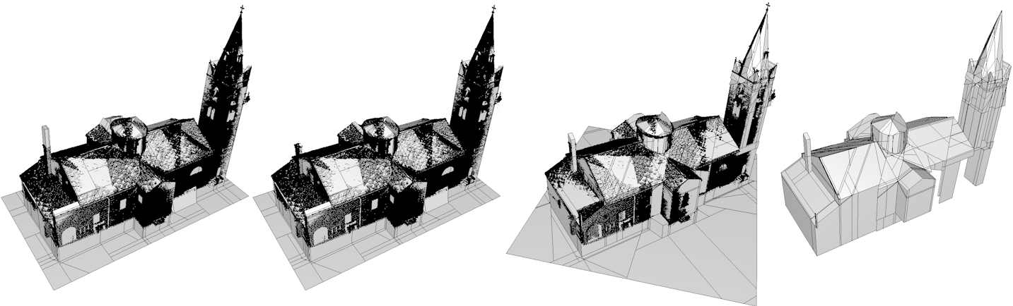
Figure 69.2 Impact of parameters on the reconstruction of the rotated lans model.
From left to right: 1. & 2. Reconstruction with using \(\lambda = 0.7\) and \(\lambda = 0.8\). A higher value of lambda removes some details on the roof as well as the chimney. As no planar shape was detected at the top of the chimney, the kinetic space partition does not offer a volume that well covers the point cloud. The volume of the chimney is either too large for \(\lambda = 0.7\) or gets cut completely for \(\lambda = 0.8\) 3. Reconstruction of the model without reorienting the bbox. For the reconstruction to succeed it is necessary to set the external_node for ZMIN to inside as the point cloud does not close the church from below. 4. Reconstruction as in 3., but without setting external_node for ZMIN.


Examples

Basic Example

This minimal example shows the import of a simple synthetic point cloud and an reconstruction using mostly default parameters.


File Kinetic_surface_reconstruction/ksr_basic.cpp

#include <CGAL/Exact_predicates_inexact_constructions_kernel.h>
#include <CGAL/Kinetic_surface_reconstruction_3.h>
#include <CGAL/Point_set_3.h>
#include <CGAL/Point_set_3/IO.h>
#include <CGAL/IO/polygon_soup_io.h>
using FT = typename Kernel::FT;
using Point_3 = typename Kernel::Point_3;
using Vector_3 = typename Kernel::Vector_3;
using Segment_3 = typename Kernel::Segment_3;
using Point_set = CGAL::Point_set_3<Point_3>;
using Point_map = typename Point_set::Point_map;
using Normal_map = typename Point_set::Vector_map;
int main() {
// Input.
Point_set point_set;
CGAL::IO::read_point_set(CGAL::data_file_path("points_3/building.ply"), point_set);
auto param = CGAL::parameters::maximum_distance(0.5)
.maximum_angle(10)
.k_neighbors(12)
.minimum_region_size(50);
// Algorithm.
KSR ksr(point_set, param);
ksr.detection_and_partition(1, param);
std::cout << ksr.detect_planar_shapes() << " planar shapes detected" << std::endl;
std::vector<Point_3> vtx;
std::vector<std::vector<std::size_t> > polylist;
ksr.reconstruct_with_ground(0.5, std::back_inserter(vtx), std::back_inserter(polylist));
if (polylist.size() > 0) {
std::cout << polylist.size() << " faces in reconstruction" << std::endl;
CGAL::IO::write_polygon_soup("building_0.5.ply", vtx, polylist);
return EXIT_SUCCESS;
}
else {
std::cout << "Reconstruction empty!" << std::endl;
return EXIT_FAILURE;
}
}
Pipeline for piecewise planar surface reconstruction from a point cloud via inside/outside labeling o...
Definition: Kinetic_surface_reconstruction_3.h:60

Building Example

This example shows the import of an acquired point cloud of a building and a reconstruction using a common choice of parameters for building reconstruction. The input point cloud is reoriented to be axis-aligned and regularization is used to simplify the detected shapes before reconstruction. The actual reconstruction method is actually fast. To avoid running the full shape detection and kinetic partition just to try different values for beta, several reconstructions are performed and exported into ply format.


File Kinetic_surface_reconstruction/ksr_building.cpp

#include <CGAL/Exact_predicates_inexact_constructions_kernel.h>
#include <CGAL/Kinetic_surface_reconstruction_3.h>
#include <CGAL/Point_set_3.h>
#include <CGAL/Point_set_3/IO.h>
#include <CGAL/IO/polygon_soup_io.h>
using FT = typename Kernel::FT;
using Point_3 = typename Kernel::Point_3;
using Vector_3 = typename Kernel::Vector_3;
using Segment_3 = typename Kernel::Segment_3;
using Point_set = CGAL::Point_set_3<Point_3>;
using Point_map = typename Point_set::Point_map;
using Normal_map = typename Point_set::Vector_map;
int main(const int, const char**) {
// Input.
Point_set point_set;
CGAL::IO::read_point_set(CGAL::data_file_path("points_3/building.ply"), point_set);
auto param = CGAL::parameters::maximum_distance(0.1)
.maximum_angle(10)
.minimum_region_size(100)
.reorient_bbox(true)
.regularize_parallelism(true)
.regularize_coplanarity(true)
.angle_tolerance(5)
.maximum_offset(0.02);
// Algorithm.
KSR ksr(point_set, param);
ksr.detection_and_partition(2, param);
std::vector<Point_3> vtx;
std::vector<std::vector<std::size_t> > polylist;
std::vector<FT> lambdas{0.3, 0.5, 0.7, 0.8, 0.9, 0.95, 0.99};
bool non_empty = false;
for (FT l : lambdas) {
vtx.clear();
polylist.clear();
ksr.reconstruct_with_ground(l, std::back_inserter(vtx), std::back_inserter(polylist));
if (polylist.size() > 0) {
non_empty = true;
CGAL::IO::write_polygon_soup("polylist_" + std::to_string(l) + ".ply", vtx, polylist);
}
}
return (non_empty) ? EXIT_SUCCESS : EXIT_FAILURE;
}

Parameters Example

This example provides a command line version of the kinetic surface reconstruction allowing to configure the input point cloud filename and most parameters.


File Kinetic_surface_reconstruction/ksr_parameters.cpp

#include <CGAL/Exact_predicates_inexact_constructions_kernel.h>
#include <CGAL/Kinetic_surface_reconstruction_3.h>
#include <CGAL/Point_set_3.h>
#include <CGAL/Point_set_3/IO.h>
#include <CGAL/Real_timer.h>
#include <CGAL/IO/PLY.h>
#include <CGAL/IO/polygon_soup_io.h>
#include <CGAL/pca_estimate_normals.h>
#include <CGAL/mst_orient_normals.h>
#include <CGAL/bounding_box.h>
#include <sstream>
#include "include/Parameters.h"
#include "include/Terminal_parser.h"
using FT = typename Kernel::FT;
using Point_3 = typename Kernel::Point_3;
using Vector_3 = typename Kernel::Vector_3;
using Segment_3 = typename Kernel::Segment_3;
using Point_set = CGAL::Point_set_3<Point_3>;
using Point_map = typename Point_set::Point_map;
using Normal_map = typename Point_set::Vector_map;
using Parameters = CGAL::KSR::All_parameters<FT>;
using Terminal_parser = CGAL::KSR::Terminal_parser<FT>;
using Timer = CGAL::Real_timer;
template <typename T>
std::string to_stringp(const T a_value, const int n = 6)
{
std::ostringstream out;
out.precision(n);
out << std::fixed << a_value;
return out.str();
}
void parse_terminal(Terminal_parser& parser, Parameters& parameters) {
// Set all parameters that can be loaded from the terminal.
// add_str_parameter - adds a string-type parameter
// add_val_parameter - adds a scalar-type parameter
// add_bool_parameter - adds a boolean parameter
std::cout << std::endl;
std::cout << "--- INPUT PARAMETERS: " << std::endl;
parser.add_str_parameter("-data", parameters.data);
// Shape detection.
parser.add_val_parameter("-kn" , parameters.k_neighbors);
parser.add_val_parameter("-dist" , parameters.maximum_distance);
parser.add_val_parameter("-angle", parameters.maximum_angle);
parser.add_val_parameter("-minp" , parameters.min_region_size);
// Shape regularization.
parser.add_bool_parameter("-regparallel", parameters.regparallel);
parser.add_bool_parameter("-regcoplanar", parameters.regcoplanar);
parser.add_bool_parameter("-regorthogonal", parameters.regorthogonal);
parser.add_bool_parameter("-regsymmetric", parameters.regsymmetric);
parser.add_val_parameter("-regoff", parameters.maximum_offset);
parser.add_val_parameter("-regangle", parameters.angle_tolerance);
// Shape regularization.
parser.add_bool_parameter("-reorient", parameters.reorient);
// Partitioning.
parser.add_val_parameter("-k", parameters.k_intersections);
parser.add_val_parameter("-odepth", parameters.max_octree_depth);
parser.add_val_parameter("-osize", parameters.max_octree_node_size);
// Reconstruction.
parser.add_val_parameter("-lambda", parameters.graphcut_lambda);
parser.add_val_parameter("-ground", parameters.use_ground);
// Debug.
parser.add_bool_parameter("-debug", parameters.debug);
// Verbose.
parser.add_bool_parameter("-verbose", parameters.verbose);
}
int main(const int argc, const char** argv) {
// Parameters.
std::cout.precision(20);
std::cout << std::endl;
std::cout << "--- PARSING INPUT: " << std::endl;
const auto kernel_name = boost::typeindex::type_id<Kernel>().pretty_name();
std::cout << "* used kernel: " << kernel_name << std::endl;
const std::string path_to_save = "";
Terminal_parser parser(argc, argv, path_to_save);
Parameters parameters;
parse_terminal(parser, parameters);
// If no input data is provided, use input from data directory.
if (parameters.data.empty())
parameters.data = CGAL::data_file_path("points_3/building.ply");
// Input.
Point_set point_set(parameters.with_normals);
CGAL::IO::read_point_set(parameters.data, point_set);
if (point_set.size() == 0) {
std::cout << "input file not found or empty!" << std::endl;
return EXIT_FAILURE;
}
if (!point_set.has_normal_map()) {
point_set.add_normal_map();
CGAL::pca_estimate_normals<CGAL::Parallel_if_available_tag>(point_set, 9);
CGAL::mst_orient_normals(point_set, 9);
}
for (std::size_t i = 0; i < point_set.size(); i++) {
Vector_3 n = point_set.normal(i);
if (abs(n * n) < 0.05)
std::cout << "point " << i << " does not have a proper normal" << std::endl;
}
if (parameters.maximum_distance == 0) {
CGAL::Bbox_3 bbox = CGAL::bbox_3(CGAL::make_transform_iterator_from_property_map(point_set.begin(), point_set.point_map()),
CGAL::make_transform_iterator_from_property_map(point_set.end(), point_set.point_map()));
FT d = CGAL::approximate_sqrt
((bbox.xmax() - bbox.xmin()) * (bbox.xmax() - bbox.xmin())
+ (bbox.ymax() - bbox.ymin()) * (bbox.ymax() - bbox.ymin())
+ (bbox.zmax() - bbox.zmin()) * (bbox.zmax() - bbox.zmin()));
parameters.maximum_distance = d * 0.03;
}
if (parameters.min_region_size == 0)
parameters.min_region_size = static_cast<std::atomic_size_t>(point_set.size() * 0.01);
std::cout << std::endl;
std::cout << "--- INPUT STATS: " << std::endl;
std::cout << "* number of points: " << point_set.size() << std::endl;
std::cout << "verbose " << parameters.verbose << std::endl;
std::cout << "maximum_distance " << parameters.maximum_distance << std::endl;
std::cout << "maximum_angle " << parameters.maximum_angle << std::endl;
std::cout << "min_region_size " << parameters.min_region_size << std::endl;
std::cout << "k " << parameters.k_intersections << std::endl;
std::cout << "graphcut_lambda " << parameters.graphcut_lambda << std::endl;
auto param = CGAL::parameters::maximum_distance(parameters.maximum_distance)
.maximum_angle(parameters.maximum_angle)
.k_neighbors(parameters.k_neighbors)
.minimum_region_size(parameters.min_region_size)
.debug(parameters.debug)
.verbose(parameters.verbose)
.max_octree_depth(parameters.max_octree_depth)
.max_octree_node_size(parameters.max_octree_node_size)
.reorient_bbox(parameters.reorient)
.regularize_parallelism(parameters.regparallel)
.regularize_coplanarity(parameters.regcoplanar)
.regularize_orthogonality(parameters.regorthogonal)
.regularize_axis_symmetry(parameters.regsymmetric)
.angle_tolerance(parameters.angle_tolerance)
.maximum_offset(parameters.maximum_offset);
// Algorithm.
KSR ksr(point_set, param);
Timer timer;
timer.start();
std::size_t num_shapes = ksr.detect_planar_shapes(param);
std::cout << num_shapes << " detected planar shapes" << std::endl;
FT after_shape_detection = timer.time();
ksr.initialize_partition(param);
FT after_init = timer.time();
ksr.partition(parameters.k_intersections);
FT after_partition = timer.time();
std::vector<Point_3> vtx;
std::vector<std::vector<std::size_t> > polylist;
std::map<typename KSR::KSP::Face_support, bool> external_nodes;
if (parameters.use_ground) {
external_nodes[KSR::KSP::Face_support::ZMIN] = false;
ksr.reconstruct_with_ground(parameters.graphcut_lambda, std::back_inserter(vtx), std::back_inserter(polylist));
}
else
ksr.reconstruct(parameters.graphcut_lambda, external_nodes, std::back_inserter(vtx), std::back_inserter(polylist));
FT after_reconstruction = timer.time();
if (polylist.size() > 0)
CGAL::IO::write_polygon_soup("polylist_" + std::to_string(parameters.graphcut_lambda) + (parameters.use_ground ? "_g" : "_") + ".off", vtx, polylist);
timer.stop();
const FT time = static_cast<FT>(timer.time());
std::vector<FT> lambdas{0.3, 0.5, 0.6, 0.7, 0.73, 0.75, 0.77, 0.8, 0.9, 0.95, 0.99};
bool non_empty = false;
for (FT l : lambdas) {
if (l == parameters.graphcut_lambda)
continue;
vtx.clear();
polylist.clear();
if (parameters.use_ground)
ksr.reconstruct_with_ground(l, std::back_inserter(vtx), std::back_inserter(polylist));
else
ksr.reconstruct(l, external_nodes, std::back_inserter(vtx), std::back_inserter(polylist));
if (polylist.size() > 0) {
non_empty = true;
CGAL::IO::write_polygon_soup("polylist_" + std::to_string(l) + (parameters.use_ground ? "_g" : "_") + ".off", vtx, polylist);
}
}
std::cout << "Shape detection: " << after_shape_detection << " seconds!" << std::endl;
std::cout << "Kinetic partition: " << (after_partition - after_shape_detection) << " seconds!" << std::endl;
std::cout << " initialization: " << (after_init - after_shape_detection) << " seconds!" << std::endl;
std::cout << " partition: " << (after_partition - after_init) << " seconds!" << std::endl;
std::cout << "Kinetic reconstruction: " << (after_reconstruction - after_partition) << " seconds!" << std::endl;
std::cout << "Total time: " << time << " seconds!" << std::endl << std::endl;
return (non_empty) ? EXIT_SUCCESS : EXIT_FAILURE;
}
double ymin() const
double xmax() const
double zmin() const
double zmax() const
double ymax() const
double xmin() const
CGAL::Bbox_3 bbox(const PolygonMesh &pmesh, const NamedParameters &np=parameters::default_values())

Performance

Kinetic surface reconstruction is aimed at reconstructing piece-wise planar objects, e.g., man-made objects and architecture. Reconstruction results on point clouds acquired from architecture in different qualities are shown in figure Figure 69.3 in the first and last row. Synthetic point clouds from a CAD model and a fractal object are shown in rows 2 and three. The datasets used here are available at https://files.inria.fr/titane/KSR42_dataset.zip.

However, also smooth surfaces can be reconstructed to a certain level of detail as is shown on the fourth row. While the scales of the dragon are not replicated with their smooth boundary, each scale can still be recognized in the final model.

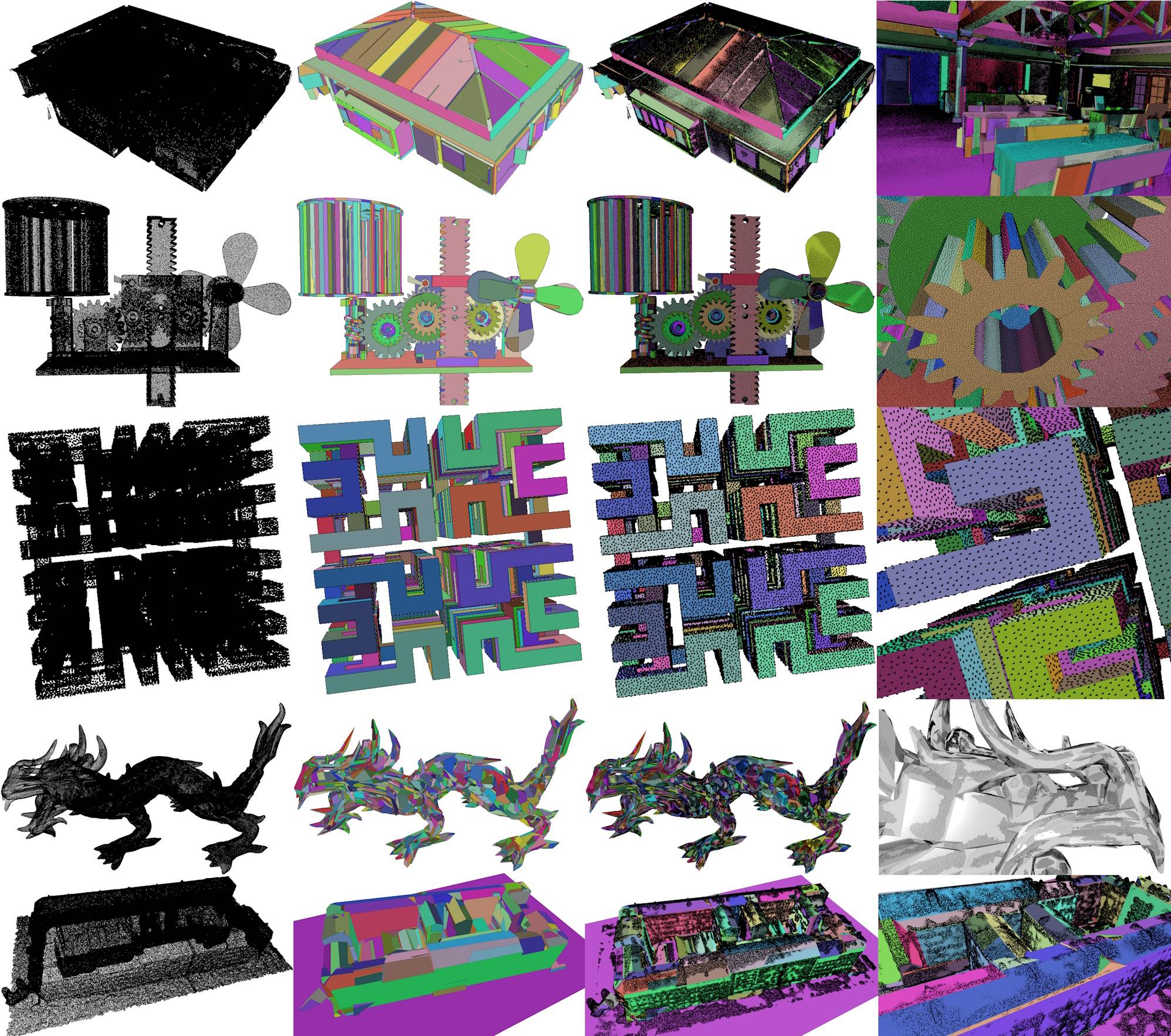
Figure 69.3 Results of kinetic surface reconstruction.
From left to right: 1. input point cloud 2. reconstructed polygon mesh 3. overlay of input and result 4. detail view.
From top to bottom: 1. Meeting room. Reconstruction of the roof framework is not perfect due to missing data. 2. Full Thing. Synthetic point cloud sampled from a CAD model. All details are well reconstructed 3. Hilbert cube. Synthetic point cloud from a fractal object. 4. Asian Dragon. Acquired point cloud from the Stanford 3D Scanning Repository. 5. Building_C. Point Cloud from multi view stereo.


The running time of the method depends mostly on the shape detection and the kinetic space partition steps. While running time of the shape detection scales with the complexity of the point cloud, the kinetic space partition depends on the number of input polygons. The running time of the shape regularization and the min-cut have not been listed, as they are <1 seconds in all cases besides the Asian Dragon with 2,75s for the min-cut.


Data set Points Detected shapes Regularized shapes Volumes in partition Polygons in reconstruction Vertices in reconstruction Shape Detection Kinetic Space Partition Total Time

Foam_box 382.059 103 60 998 97 444 6,5 3,3 9,8
Lans 1.220.459 324 169 3.334 330 1.175 26,3 9,4 35,7
Meeting Room 3.074.625 1.652 777 29.605 2.867 11.819 37,1 93,4 131,1
Full Thing 1.377.666 1.947 1.790 21.804 2.655 12.984 8,6 238,8 248,2
Hilbert cube 144.092 968 48 5.778 986 4.124 0,6 10,5 11,1
Asian Dragon 3.609.455 2.842 2.842 101.651 10.209 34.237 31,2 757,5 790,7
Building_C 1.000.000 221 172 3.432 370 1.466 40,1 12,3 52,4

The parameters to reconstruct these models are available in the following table:


Data set Maximum distance Maximum angle Minimum region size K nearest neighbors Regularize parallelism
Angle tolerance
Regularize coplanarity
Maximum offset
K Lambda

Foam_box 0,05 15 250 12 10 0,01 2 0,7
Lans 0,15 20 300 12 8 0,08 2 0,7
Meeting Room 0,03 19 100 15 0,03 10 3 0,5
Full Thing 0,3 36 30 12 0,05 3 1 0,5
Hilbert cube 0,3 10 10 12 0,03 5 4 0,5
Asian Dragon 0,7 26 150 10 0 0 1 0,75
Building_C 1,1 26 500 15 0,5 3 2 0,77

Design and Implementation History

This package is an implementation of Bauchet et. al [1]. A proof of concept of the kinetic surface reconstruction was developed by Dmitry Anisimov.