Fernando Cacciola
A 2D contour is a closed sequence (a cycle) of 3 or more connected 2D oriented straight line segments called contour edges. The endpoints of the contour edges are called vertices. Each contour edge shares its endpoints with at least two other contour edges.
If the edges intersect only at the vertices and at most are coincident along a line but do not cross one another, the contour is classified as simple.
A contour is topologically equivalent to a disk and if it is simple, is said to be a Jordan Curve.
Contours partition the plane in two open regions: one bounded and one unbounded. If the bounded region of a contour is a singly-connected set, the contour is said to be strictly-simple.
The Orientation of a contour is given by the order of the vertices around the region they bound. It can be Clockwise (CCW) or Counter-clockwise (CW).
The bounded side of a contour edge is the side facing the bounded region of the contour. If the contour is oriented CCW, the bounded side of an edge is its left side.
A contour with a null edge (a segment of length zero given by two consecutive coincident vertices), or with edges not connected to the bounded region (an antenna: 2 consecutive edges going forth and back along the same line), is said to be degenerate (collinear edges are not considered a degeneracy).
A 2D polygon is a contour.
A 2D polygon with holes is a contour, called the outer contour, having zero or more contours, called inner contours, or holes, in its bounded region. The intersection of the bounded region of the outer contour and the unbounded regions of each inner contour is the interior of the polygon with holes. The orientation of the holes must be opposite to the orientation of the outer contour and there cannot be any intersection among any contour. A hole cannot be in the bounded region of any other hole.
A polygon with holes is strictly-simple if its interior is a singly-connected set.
The orientation of a polygon with holes is the orientation of its outer contour. The bounded side of any edge, whether of the outer contour or a hole, is the same for all edges. That is, if the outer contour is oriented CCW and the holes CW, both contour and hole edges face the polygon interior to their left.
Throughout the rest of this chapter the term polygon will be used as a shortcut for polygon with holes.
For any 2D non-degenerate strictly-simple polygon with holes called the source, there can exist a set of 0, 1 or more inward offset polygons with holes, or just offset polygons for short, at some euclidean distance t (each being strictly simple and non-degenerate). Any contour edge of such offset polygon, called an offset edge corresponds to some contour edge of the source polygon, called its source edge. An offset edge is parallel to its source edge and has the same orientation. The Euclidean distance between the lines supporting an offset edge and its source edge is exactly t.
An offset edge is always located to the bounded side of its source edge (which is an oriented straight line segment).
An offset polygon can have less, equal or more sides as its source polygon.
If the source polygon has no holes, no offset polygon has holes. If the source polygon has holes, any of the offset polygons can have holes itself, but it might as well have no holes at all (if the distance is sufficiently large).
Each offset polygon has the same orientation as the source polygon.
The 2D straight skeleton of a non-degenerate strictly-simple polygon with holes [AAAG95] is a special partitioning of the polygon interior into straight skeleton regions corresponding to the monotone areas traced by a continuous inward offsetting of the contour edges. Each region corresponds to exactly 1 contour edge.
These regions are bounded by angular bisectors of the supporting lines of the contour edges and each such region is itself a non-convex non-degenerate strictly-simple polygon.
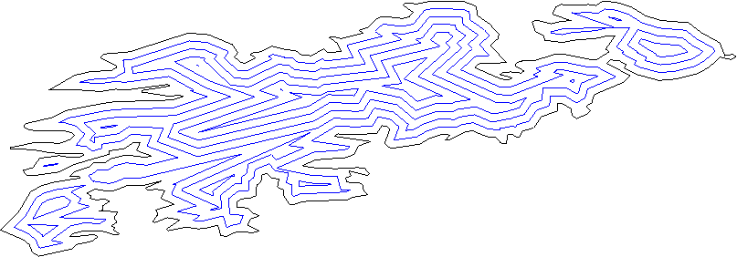
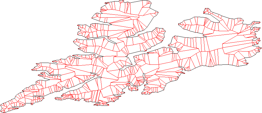
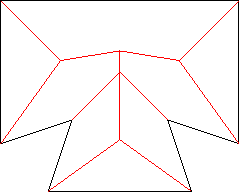
Figure: Straight skeleton of a complex shaggy contour
|
|
|
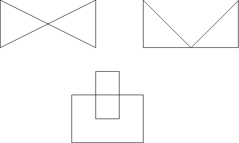
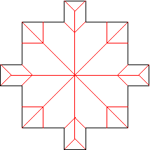
Figure: Other examples: A vertex-event (left), the case of several collinear edges (middle), and the case of a validly simple polygon with tangent edges (right).
Given two points and a line passing through them, the perpendicular line passing through the midpoint is the bisecting line (or bisector) of those points.
Two non-parallel lines, intersecting at a point, are bisected by two other lines passing through that intersection point.
Two parallel lines are bisected by another parallel line placed halfway in between.
Given just one line, any perpendicular line can be considered the bisecting line (any bisector of any two points along the single line).
The bisecting lines of two edges are the lines bisecting the supporting lines of the edges (if the edges are parallel or collinear, there is just one bisecting line).
The halfplane to the bounded side of the line supporting a contour edge is called the offset zone of the contour edge.
Given any number of contour edges (not necessarily consecutive), the intersection of their offset zones is called their combined offset zone.
Any two contour edges define an offset bisector, as follows: If the edges are non-parallel, their bisecting lines can be decomposed as 4 rays originating at the intersection of the supporting lines. Only one of these rays is contained in the combined offset zone of the edges (which one depends on the possible combinations of orientations). This ray is the offset bisector of the non-parallel contour edges.
If the edges are parallel (but not collinear) and have opposite orientation, the entire and unique bisecting line is their offset bisector. If the edges are parallel but have the same orientation, there is no offset bisector between them.
If the edges are collinear and have the same orientation, their offset bisector is given by a perpendicular ray to the left of the edges which originates at the midpoint of the combined complement of the edges. (The complement of an edge/segment are the two rays along its supporting line which are not the segment and the combined complement of N collinear segments is the intersection of the complements of each segment). If the edges are collinear but have opposite orientation, there is no offset bisector between them.
Each region of the partitioning defined by a straight skeleton is called a face. Each face is bounded by straight line segments, called edges. Exactly one edge per face is a contour edge (corresponds to a side of the polygon) and the rest of the edges, located in the interior of the polygon, are called skeleton edges, or bisectors.
The bisectors of the straight skeleton are segments of the offset bisectors as defined previously. Since an offset bisector is a ray of a bisecting line of 2 contour edges, each skeleton edge (or bisector) is uniquely given by two contour edges. These edges are called the defining contour edges of the bisector.
The intersection of the edges are called vertices. Although in a simple polygon, only 2 edges intersect at a vertex, in a straight skeleton, 3 or more edges intersect a any given vertex. That is, vertices in a straight skeleton have degree .
A contour vertex is a vertex for which 2 of its incident edges are contour edges.
A skeleton vertex is a vertex who's incident edges are all skeleton edges.
A contour bisector is a bisector who's defining contour edges are consecutive. Such a bisector is incident upon 1 contour vertex and 1 skeleton vertex and touches the input polygon at exactly 1 endpoint.
An inner bisector is a bisector who's defining contour edges are not consecutive. Such a bisector is incident upon 2 skeleton vertices and is strictly contained in the interior of the polygon.
This CGAL package represents a straight skeleton as a specialized Halfedge Data Structure (HDS) whose vertices embeds 2D Points (see the StraightSkeleton_2 concept in the reference manual for details).
Its halfedges, by considering the source and target points, implicitly embeds 2D oriented straight line segments (each halfedge per see does not embed a segment explicitly).
A face of the straight skeleton is represented as a face in the HDS. Both contour and skeleton edges are represented by pairs of opposite HDS halfedges, and both contour and skeleton vertices are represented by HDS vertices.
In a HDS, a border halfedge is a halfedge which is incident upon an unbounded face. In the case of the straight skeleton HDS, such border halfedges are oriented such that their left side faces outwards the polygon. Therefore, the opposite halfedge of any border halfedge is oriented such that its left side faces inward the polygon.
This CGAL package requires the input polygon (with holes) to be non-degenerate, strictly-simple, and oriented counter-clockwise.
The skeleton halfedges are oriented such that their left side faces inward the region they bound. That is, the vertices (both contour and skeleton) of a face are circulated in counter-clockwise order. There is one and only one contour halfedge incident upon any face.
The contours of the input polygon are traced by the border halfedges of the HDS (those facing outward), but in the opposite direction. That is, the vertices of the contours can only by traced from the straight skeleton data structure by circulating the border halfedges, and the resulting vertex sequence will be reversed w.r.t the input vertex sequence.
A skeleton edge, according to the definition given in the previous section, is defined by 2 contour edges. In the representation, each one of the opposite halfedges that represent a skeleton edge is associated with one of the opposite halfedges that correspond to one of its defining contour edges. Thus, the 2 opposite halfedges of a skeleton edge link the edge to its 2 defining contour edges.
Starting from any border contour halfedge, circulating the structure walks through border counter halfedges and traces the vertices of the polygon's contours (in opposite order).
Starting from any non-border but contour halfedge, circulating the structure walks counter-clockwise around the face corresponding to that contour halfedge. The vertices around a face always describe a non-convex non-degenerate strictly-simple polygon.
A vertex is the intersection of contour and/or skeleton edges. Since a skeleton edge is defined by 2 contour edges, any vertex is itself defined by a unique set of contour edges. These are called the defining contour edges of the vertex.
A vertex is identified by it's set of defining contour edges. Two vertices are distinct if they have differing sets of defining contour edges. Note that vertices can be distinct even if they are geometrically embedded at the same point.
The degree of a vertex is the number of halfedges around the vertex incident upon (pointing to) the vertex. As with any halfedge data structure, there is one outgoing halfedge for each incoming (incident) halfedge around a vertex. The degree of the vertex counts only incoming (incident) halfedges.
In a straight skeleton, the degree of a vertex is not only the number of incident halfedges around the vertex but also the number of defining contour halfedges. The vertex itself is the point where all the defining contour edges simultaneously collide.
Contour vertices have exactly two defining contour halfedges, which are the contour edges incident upon the vertex; and 3 incident halfedges. One and only one of the incident halfedges is a skeleton halfedge. The degree of a contour vertex is exactly 3.
Skeleton vertices have at least 3 defining contour halfedges and 3 incident skeleton halfedges. If more than 3 edges collide simultaneously at the same point and time (like in any regular polygon with more than 3 sides), the corresponding skeleton vertex will have more than 3 defining contour halfedges and incident skeleton halfedges. That is, the degree of a skeleton vertex is (the algorithm initially produces nodes of degree 3 but in the end all coincident nodes are merged to form higher degree nodes). All halfedges incident upon a skeleton vertex are skeleton halfedges.
The defining contour halfedges and incident halfedges around a vertex can be traced using the circulators provided by the vertex class. The degree of a vertex is not cached and cannot be directly obtained from the vertex, but you can calculate this number by manually counting the number of incident halfedges around the vertex.
Each vertex stores a 2D point and a time, which is the euclidean distance from the vertex's point to the lines supporting each of the defining contour edges of the vertex (the distance is the same to each line). Unless the polygon is convex, this distance is not equidistant to the edges, as in the case of a Medial Axis, therefore, the time of a skeleton vertex does not correspond to the distance from the polygon to the vertex (so it cannot be used to obtain the deep of a region in a shape, for instance).
If the polygon is convex, the straight skeleton is exactly equivalent to the polygon's voronoi diagram and each vertex time is the equidistance to the defining edges.
Contour vertices have time zero.
|
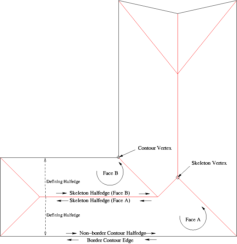
Figure: Straight Skeleton Data Structure
The straight skeleton data structure is defined by the StraightSkeleton_2 concept and modeled in the Straight_skeleton_2<Traits,Items,Alloc> class.
The straight skeleton construction algorithm is encapsulated in the class Straight_skeleton_builder_2<Gt,Ss> which is parameterized on a geometric traits (class Straight_skeleton_builder_traits<Kernel>) and the Straight Skeleton class (Ss).
The offset contours construction algorithm is encapsulated in the class Polygon_offset_builder_2<Ss,Gt,Container> which is parameterized on the Straight Skeleton class (Ss), a geometric traits (class Polygon_offset_builder_traits<Kernel>) and a container type where the resulting offset polygons are generated.
To construct the straight skeleton of a polygon with holes the user must:
(1) Instantiate the straight skeleton builder.
(2) Enter one contour at a time, starting from the outer contour, via the method enter_contour. The input polygon with holes must be non-degenerate, strictly-simple and counter-clockwise oriented (see the definitions at the beginning of this chapter). Collinear edges are allowed. The insertion order of each hole is unimportant but the outer contour must be entered first.
(3) Call construct_skeleton once all the contours have been entered. You cannot enter another contour once the skeleton has been constructed.
To construct a set of inward offset contours the user must:
(1) Construct the straight skeleton of the source polygon with holes.
(2) Instantiate the polygon offset builder passing in the straight skeleton as a parameter.
(3) Call construct_offset_contours passing the desired offset distance and an output iterator that can store a boost::shared_ptr of Container instances into a resulting sequence (typically, a back insertion iterator)
Each element in the resulting sequence is an offset contour, given by a boost::shared_ptr holding a dynamically allocated instance of the Container type. Such a container can be any model of the VertexContainer_2 concept, for example, a CGAL::Polygon_2, or just a std::vector of 2D points.
The resulting sequence of offset contours can contain both outer and inner contours. Each offset hole (inner offset contour) would logically belong in the interior of some of the outer offset contours. However, this algorithm returns a sequence of contours in arbitrary order and there is no indication whatsoever of the parental relationship between inner and outer contours.
On the other hand, each outer contour is counter-clockwise oriented while each hole is clockwise-oriented. And since offset contours do form simple polygons with holes, it is guaranteed that no hole will be inside another hole, no outer contour will be inside any other contour, and each hole will be inside exactly 1 outer contour.
Parental relationships are not automatically reconstructed by this algorithm because this relation is not directly given by the input polygon with holes and doing it robustly is a time-consuming operation.
A user can reconstruct the parental relationships as a post processing operation by testing each inner contour (which is identified by being clockwise) against each outer contour (identified as being counter-clockwise) for insideness.
This algorithm requires exact predicates but not exact constructions Therefore, the Exact_predicates_inexact_constructions_kernel should be used.
This CGAL package can only construct the straight skeleton and offset contours in the interior of a polygon with holes. However, constructing exterior skeletons and exterior offsets is possible:
Say you have some polygon made of 1 outer contour C0 and 1 hole C1, and you need to obtain some exterior offset contours.
The interior region of a polygon with holes is connected while the exterior region is not: there is an unbounded region outside the outer contour, and one bounded region inside each hole.
To construct an offset contour you need to construct an straight skeleton. Thus, to construct exterior offset contours for a polygon with holes, you need to construct, separately, the exterior skeleton of the outer contour and the interior skeleton of each hole.
Constructing the interior skeleton of a hole is directly supported by this CGAL package; you just need to input the hole's vertices in reversed order as if it were an outer contour.
Constructing the exterior skeleton of the outer contour is possible by means of the following trick: place the contour as a hole of a big rectangle (call it frame). If the frame is sufficiently separated from the contour, the resulting skeleton will be practically equivalent to a real exterior skeleton.
To construct exterior offset contours in the inside of each hole you just use the skeleton constructed in the interior, and, if required, revert the orientation of each resulting offset contour.
Constructing exterior offset contours in the outside of the outer contour is just a little bit more involved: Since the contour is placed as a hole of a frame, you will always obtain 2 offset contours for any given distance; one is the offseted frame and the other is the offseted contour. Thus, from the resulting offset contour sequence, you always need to discard the offsetted frame, easily identified as the offset contour with the largest area.
It is necessary to place the frame sufficiently away from the contour. If it is not, it could occur that the outward offset contour collides and merges with the inward offset frame, resulting in 1 instead of 2 offset contours.
However, the proper separation between the contour and the frame is not directly given by the offset distance at which you want the offset contour. That distance must be at least the desired offset plus the largest euclidean distance between an offset vertex and its original.
This CGAL packages provides a helper function to compute the required separation:
compute_outer_frame_margin
If you use this function to place the outer frame you are guaranteed to obtain an offset contour corresponding exclusively to the frame, which you can always identify as the one with the largest area and which you can simple remove from the result (to keep just the relevant outer contours).
|
|
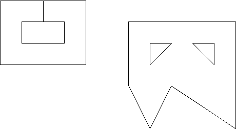
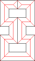
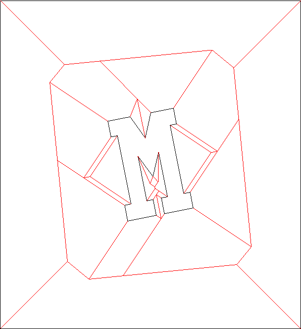
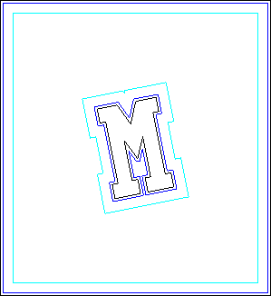
Figure: Exterior skeleton obtained using a frame (left) and 2 sample exterior offset contours (right)
#include<vector>
#include<iterator>
#include<iostream>
#include<iomanip>
#include<string>

#include<boost/shared_ptr.hpp>

#include<CGAL/basic.h>
#include<CGAL/Cartesian.h>
#include<CGAL/Polygon_2.h>
#include<CGAL/Exact_predicates_inexact_constructions_kernel.h>
#include<CGAL/Straight_skeleton_builder_2.h>
#include<CGAL/Polygon_offset_builder_2.h>
#include<CGAL/compute_outer_frame_margin.h>

//
// This example illustrates how to use the CGAL Straight Skeleton package
// to construct an offset contour on the outside of a polygon
//

// This is the recommended kernel
typedef CGAL::Exact_predicates_inexact_constructions_kernel Kernel;

typedef Kernel::Point_2 Point_2;
typedef CGAL::Polygon_2<Kernel>    Contour;
typedef boost::shared_ptr<Contour> ContourPtr;
typedef std::vector<ContourPtr>    ContourSequence ;

typedef CGAL::Straight_skeleton_2<Kernel> Ss;

typedef Ss::Halfedge_iterator Halfedge_iterator;
typedef Ss::Halfedge_handle   Halfedge_handle;
typedef Ss::Vertex_handle     Vertex_handle;

typedef CGAL::Straight_skeleton_builder_traits_2<Kernel>      SsBuilderTraits;
typedef CGAL::Straight_skeleton_builder_2<SsBuilderTraits,Ss> SsBuilder;

typedef CGAL::Polygon_offset_builder_traits_2<Kernel>                  OffsetBuilderTraits;
typedef CGAL::Polygon_offset_builder_2<Ss,OffsetBuilderTraits,Contour> OffsetBuilder;

int main()
{
  // A start-shaped polygon, oriented counter-clockwise as required for outer contours.
  Point_2 pts[] = { Point_2(-1,-1)
                  , Point_2(0,-12)
                  , Point_2(1,-1)
                  , Point_2(12,0)
                  , Point_2(1,1)
                  , Point_2(0,12)
                  , Point_2(-1,1)
                  , Point_2(-12,0)
                  } ;

  std::vector<Point_2> star(pts,pts+8);

  // We want an offset contour in the outside.
  // Since the package doesn't support that operation directly, we use the following trick:
  // (1) Place the polygon as a hole of a big outer frame.
  // (2) Construct the skeleton on the interior of that frame (with the polygon as a hole)
  // (3) Construc the offset contours
  // (4) Identify the offset contour that corresponds to the frame and remove it from the result


  double offset = 3 ; // The offset distance

  // First we need to determine the proper separation between the polygon and the frame.
  // We use this helper function provided in the package.
  boost::optional<double> margin = CGAL::compute_outer_frame_margin(star.begin(),star.end(),offset);

  // Proceed only if the margin was computed (an extremely sharp corner might cause overflow)
  if ( margin )
  {
    // Get the bbox of the polygon
    CGAL::Bbox_2 bbox = CGAL::bbox_2(star.begin(),star.end());

    // Compute the boundaries of the frame
    double fxmin = bbox.xmin() - *margin ;
    double fxmax = bbox.xmax() + *margin ;
    double fymin = bbox.ymin() - *margin ;
    double fymax = bbox.ymax() + *margin ;

    // Create the rectangular frame
    Point_2 frame[4]= { Point_2(fxmin,fymin)
                      , Point_2(fxmax,fymin)
                      , Point_2(fxmax,fymax)
                      , Point_2(fxmin,fymax)
                      } ;

    // Instantiate the skeleton builder
    SsBuilder ssb ;

    // Enter the frame
    ssb.enter_contour(frame,frame+4);

    // Enter the polygon as a hole of the frame (NOTE: as it is a hole we insert it in the opposite orientation)
    ssb.enter_contour(star.rbegin(),star.rend());

    // Construct the skeleton
    boost::shared_ptr<Ss> ss = ssb.construct_skeleton();

    // Proceed only if the skeleton was correctly constructed.
    if ( ss )
    {
      // Instantiate the container of offset contours
      ContourSequence offset_contours ;

      // Instantiate the offset builder with the skeleton
      OffsetBuilder ob(*ss);

      // Obtain the offset contours
      ob.construct_offset_contours(offset, std::back_inserter(offset_contours));

      // Locate the offset contour that corresponds to the frame
      // That must be the outmost offset contour, which in turn must be the one
      // with the largetst unsigned area.
      ContourSequence::iterator f = offset_contours.end();
      double lLargestArea = 0.0 ;
      for (ContourSequence::iterator i = offset_contours.begin(); i != offset_contours.end(); ++ i  )
      {
        double lArea = CGAL_NTS abs( (*i)->area() ) ; //Take abs() as  Polygon_2::area() is signed.
        if ( lArea > lLargestArea )
        {
          f = i ;
          lLargestArea = lArea ;
        }
      }

      // Remove the offset contour that corresponds to the frame.
      offset_contours.erase(f);


      // Print out the skeleton
      Halfedge_handle null_halfedge ;
      Vertex_handle   null_vertex ;

      // Dump the edges of the skeleton
      for ( Halfedge_iterator i = ss->halfedges_begin(); i != ss->halfedges_end(); ++i )
      {
        std::string edge_type = (i->is_bisector())? "bisector" : "contour";
        Vertex_handle s = i->opposite()->vertex();
        Vertex_handle t = i->vertex();
        std::cout << "(" << s->point() << ")->(" << t->point() << ") " << edge_type << std::endl;
      }

      // Dump the generated offset polygons

      std::cout << offset_contours.size() << " offset contours obtained\n" ;

      for (ContourSequence::const_iterator i = offset_contours.begin(); i != offset_contours.end(); ++ i )
      {
        // Each element in the offset_contours sequence is a shared pointer to a Polygon_2 instance.

        std::cout << (*i)->size() << " vertices in offset contour\n" ;

        for (Contour::Vertex_const_iterator j = (*i)->vertices_begin(); j != (*i)->vertices_end(); ++ j )
           std::cout << "(" << j->x() << "," << j->y() << ")" << std::endl ;
      }
    }
  }

  return 0;
}
The straight skeleton of a polygon is similar to the medial axis and the voronoi diagram of a polygon in the way it partitions it; however, unlike the medial axis and voronoi diagram, the bisectors are not equidistant to its defining edges but to the supporting lines of such edges. As a result, Straight Skeleton bisectors might not be located in the center of the polygon and so cannot be regarded as a proper Medial Axis in its geometrical meaning.
On the other hand, only reflex vertices (whose internal angle ) are the source of deviations of the bisectors from its center location. Therefore, for convex polygons, the straight skeleton, the medial axis and the Voronoi diagram are exactly equivalent, and, if a non-convex polygon contains only vertices of low reflexivity, the straight skeleton bisectors will be placed nearly equidistant to their defining edges, producing a straight skeleton pretty much alike a proper medial axis.
The most natural usage of straight skeletons is offsetting: growing and shrinking polygons (provided by this CGAL package).
Anther usage, perhaps its very first, is roof design: The straight skeleton of a polygonal roof directly gives the layout of each tent. If each skeleton edge is lifted from the plane a height equal to its offset distance, the resulting roof is "correct" in that water will always fall down to the contour edges (roof border) regardless of were in the roof it falls. [LD03] gives an algorithm for roof design based on the straight skeleton.
Just like medial axes, 2D straight skeletons can also be used for 2D shape description and matching. Essentially, all the applications of image-based skeletonization (for which there is a vast literature) are also direct applications of the straight skeleton, specially since skeleton edges are simply straight line segments.
Consider the subgraph formed only by inner bisectors (that is, only the skeleton halfeges which are not incident upon a contour vertex). Call this subgraph a skeleton axis. Each node in the skeleton axis whose degree is roots more than one skeleton tree. Each skeleton tree roughly corresponds to a region in the input topologically equivalent to a rectangle; that is, without branches. For example, a simple letter "H" would contain 2 higher degree nodes separating the skeleton axis in 5 trees; while the letter "@" would contain just 1 higher degree node separating the skeleton axis in 2 curly trees.
Since a skeleton edge is a 2D straight line, each branch in a skeleton tree is a polyline. Thus, the path-length of the tree can be directly computed. Furthermore, the polyline for a particular tree can be interpolated to obtain curve-related information.
Pruning each skeleton tree cutting off branches whose length is below some threshold; or smoothing a given branch, can be used to reconstruct the polygon without undesired details, or fit into a particular canonical shape.
Each skeleton edge in a skeleton branch is associated with 2 contour edges which are facing each other. If the polygon has a bottleneck (it almost touches itself), a search in the the skeleton graph measuring the distance between each pair of contour edges will reveal the location of the bottleneck, allowing you to cut the shape in two. Likewise, if two shapes are too close to each other along some part of their boundaries (a near contact zone), a similar search in an exterior skeleton of the two shapes at once would reveal the parts of near contact, allowing you to stitch the shapes. These cut and stitch operations can be directly executed in the straight skeleton itself instead of the input polygon (because the straight skeleton contains a graph of the connected contour edges).
A straight skeleton can also be defined for a general multiply-connected planar directed straight-line graph [AA95] by considering all the edges as embedded in an unbounded region. The only difference is that in this case some faces will be only partially bounded.
The current version of this CGAL package can only construct the straight skeleton in the interior of a simple polygon with holes, that is it doesn't handle general polygonal figures in the plane.