|
CGAL 4.14.1 - 2D Triangulation
|
|
CGAL 4.14.1 - 2D Triangulation
|
This chapter describes the two dimensional triangulations of CGAL. Section Definitions recalls the main definitions about triangulations. Section Representation discusses the way two-dimensional triangulations are represented in CGAL. Section Software Design presents the overall software design of the 2D triangulations package. The next sections present the different two dimensional triangulations classes available in CGAL: basic triangulations (Section Basic Triangulations), Delaunay triangulations (Section Delaunay Triangulations), regular triangulations (Section Regular Triangulations), constrained triangulations (Section Constrained Triangulations), and constrained Delaunay triangulations (Section Constrained Delaunay Triangulations). Section Constrained Triangulations with a Bidirectional Mapping between Constraints and Subconstraints describes a class which implements a constrained or constrained Delaunay triangulation with an additional data structure to describe how the constraints are refined by the edges of the triangulations. Section The Triangulation Hierarchy describes a hierarchical data structure for fast point location queries. At last, Section Flexibility explains how the user can benefit from the flexibility of CGAL triangulations using customized classes for faces and vertices.
A two dimensional triangulation can be roughly described as a set \( T\) of triangular facets such that:
More precisely, a triangulation can be described as a simplicial complex. Let us first record a few definitions.
A simplicial complex is a set \( T\) of simplices such that
The dimension \( d\) of a simplicial complex is the maximal dimension of its simplices.
A simplicial complex \( T\) is pure if any simplex of \( T\) is included in a simplex of \( T\) with maximal dimension.
Two simplexes in \( T\) with maximal dimension \( d\) are said to be adjacent if they share a \( d-1\) dimensional sub-face. A simplicial complex is connected if the adjacency relation defines a connected graph over the set of simplices of \( T\) with maximal dimension.
The union \( U_T\) of all simplices in \( T\) is called the domain of \( T\). A point \( p\) in the domain of \( T\) is said to singular if its surrounding in \( U_T\) is neither a topological ball nor a topological disc.
Then, a two dimensional triangulation can be described as a two dimensional simplicial complex that is pure, connected and without singularity.
Each facet of a triangulation can be given an orientation which in turn induces an orientation on the edges incident to that facet. The orientation of two adjacent facets are said to be consistent if they induce opposite orientations on their common incident edge. A triangulation is said to be orientable if the orientation of each facet can be chosen in such a way that all pairs of incident facets have consistent orientations.
The data structure underlying CGAL triangulations allows the user to represent the combinatorics of any orientable two dimensional triangulations without boundaries. On top of this data structure, the 2D triangulations classes take care of the geometric embedding of the triangulation and are designed to handle planar triangulations. The plane of the triangulation may be embedded in a higher dimensional space.
The triangulations of CGAL are complete triangulations which means that their domain is the convex hull of their vertices. Because any planar triangulation can be completed, this is not a real restriction. For instance, a triangulation of a polygonal region can be constructed and represented as a subset of a constrained triangulation in which the region boundary edges have been input as constrained edges (see Section Constrained Triangulations, Constrained Delaunay Triangulations and Constrained Triangulations with a Bidirectional Mapping between Constraints and Subconstraints).
Strictly speaking, the term face should be used to design a face of any dimension, and the two-dimensional faces of a triangulation should be properly called facets. However, following a common usage, we hereafter often call faces, the facets of a two dimensional triangulation.
A 2D triangulation of CGAL can be viewed as a planar partition whose bounded faces are triangular and cover the convex hull of the set of vertices. The single unbounded face of this partition is the complementary of the convex hull. In many applications, such as Kirkpatrick's hierarchy or incremental Delaunay construction, it is convenient to deal with only triangular faces. Therefore, a fictitious vertex, called the infinite vertex is added to the triangulation as well as infinite edges* and infinite faces incident to it. Each infinite edge is incident to the infinite vertex and to a vertex of the convex hull. Each infinite face is incident to the infinite vertex and to a convex hull edge.
Therefore, each edge of the triangulation is incident to exactly two faces and the set of faces of a triangulation is topologically equivalent to a two-dimensional sphere. This extends to lower dimensional triangulations arising in degenerate cases or when the triangulations as less than three vertices. Including the infinite faces, a one dimensional triangulation is a ring of edges and vertices topologically equivalent to a \( 1\)-sphere. A zero dimensional triangulation, whose domain is reduced to a single point, is represented by two vertices that is topologically equivalent to a \( 0\)-sphere.
Note that the infinite vertex has no significant coordinates and that no geometric predicate can be applied on it nor on an infinite face.

Because a triangulation is a set of triangular faces with constant-size complexity, triangulations are not implemented as a layer on top of a planar map. CGAL uses a proper internal representation of triangulations based on faces and vertices rather than on edges. Such a representation saves storage space and results in faster algorithms [1].
The basic elements of the representation are vertices and faces. Each triangular face gives access to its three incident vertices and to its three adjacent faces. Each vertex gives access to one of its incident faces and through that face to the circular list of its incident faces.
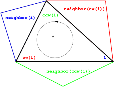
The three vertices of a face are indexed with 0, 1 and 2 in counterclockwise order. The neighbors of a face are also indexed with 0,1,2 in such a way that the neighbor indexed by i is opposite to the vertex with the same index. See Figure 39.2, the functions ccw(i) and cw(i) shown on this figure compute respectively \( i+1\) and \( i-1\) modulo 3.
The edges are not explicitly represented, they are only implicitly represented through the adjacency relations of two faces. Each edge has two implicit representations: the edge of a face f which is opposed to the vertex indexed i, can be represented as well as an edge of the neighbor(i) of f.
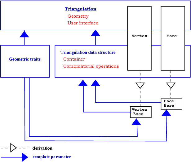
The triangulations classes of CGAL provide high-level geometric functionalities such as location of a point in the triangulation, insertion, removal, or displacement of a point. They are build as a layer on top of a data structure called the triangulation data structure. The triangulation data structure can be thought of as a container for the faces and vertices of the triangulation. This data structure also takes care of all the combinatorial aspects of the triangulation.
This separation between the geometric aspect and the combinatorial part is reflected in the software design by the fact that the triangulation classes have two template parameters:
the first parameter stands for a geometric traits class providing the geometric primitives (points, segments and triangles) of the triangulation and the elementary operations (predicate or constructions) on those objects.
the second parameter stands for a triangulation data structure class. The concept of triangulation data structure is described in Section Concepts of Chapter 2D Triangulation Data Structure. The triangulation data structure defines the types used to represent the faces and vertices of the triangulation, as well as additional types (handles, iterators and circulators) to access and visit the faces and vertices.
CGAL provides the class Triangulation_data_structure_2<Vb,Fb> as a default model of triangulation data structure. The class Triangulation_data_structure_2<Vb,Fb> has two template parameters standing for a vertex class and a face class. CGAL defines concepts for these template parameters and provide default models for these concepts. The vertex and base classes are templated by the geometric traits class which enables them to obtain some knowledge of the geometric primitives of the triangulation. Those default vertex and face base classes can be replaced by user customized base classes in order, for example, to deal with additional properties attached to the vertices or faces of a triangulation. See Section Flexibility for more details on the way to make use of this flexibility.
Figure 39.3 summarizes the design of the triangulation package, showing the three layers (base classes, triangulation data structure and triangulation) forming this design.
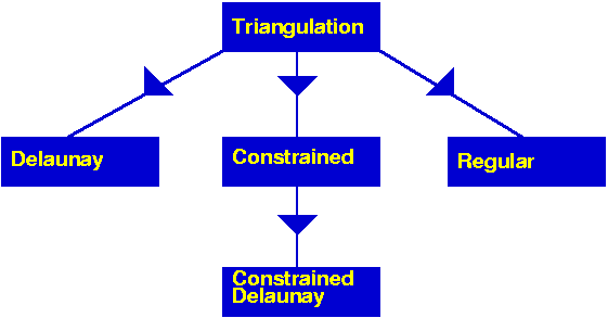
The top triangulation level, responsible for the geometric embedding of the triangulation comes in different flavors according to the different kind of triangulations: basic, Delaunay, regular, constrained or constrained Delaunay. Each kind of triangulations correspond to a different class. Figure 39.4 summarizes the derivation dependencies of CGAL 2D triangulations classes. Any 2D triangulation class is parametrized by a geometric traits class and a triangulation data structure. While a unique concept TriangulationDataStructure_2 describes the triangulation data structure requirements for any triangulation class, the requirements on the geometric traits class actually depend on the triangulation class. In general, the requirements for the vertex and face base classes are described by the basic concepts TriangulationVertexBase_2 and TriangulationFaceBase_2. However, some triangulation classes require base classes implementing refinements of the basic concepts.
The class Triangulation_2<Traits,Tds> serves as a base class for the other 2D triangulations classes and implements the user interface to a triangulation.
The vertices and faces of the triangulations are accessed through handles, iterators and circulators. A handle is a model of the concept Handle which basically offers the two dereference operators * and ->. A circulator is a type devoted to visit circular sequences. Handles are used whenever the accessed element is not part of a sequence. Iterators and circulators are used to visit all or parts of the triangulation.
The iterators and circulators are all bidirectional and non mutable. The circulators and iterators are convertible to the handles with the same value type, so that when calling a member function, any handle type argument can be replaced by an iterator or a circulator with the same value type.
The triangulation class provides a function to visit the vertices and neighbors of a face in clockwise or counterclockwise order.
There are circulators to visit the edges or faces incident to a given vertex or the vertices adjacent to it. Another circulator type enables the visit of all the faces traversed by a given line. Circulators step through infinite features as well as through finite ones.
The triangulation class offers some iterators to visit all the faces, edges or vertices and also iterators to visit selectively the finite faces, edges or vertices.
The triangulation class provides methods to test the infinite character of any feature, and also methods to test the presence in the triangulation of a particular feature (edge or face) given its vertices.
The triangulation class provides a method to locate a given point with respect to a triangulation. In particular, this method reports whether the point coincides with a vertex of the triangulation, lies on an edge, in a face or outside of the convex hull. In case of a degenerate lower dimensional triangulation, the query point may also lie outside the triangulation affine hull.
The triangulation class also provides methods to locate a point with respect to a given finite face of the triangulation or with respect to its circumcircle. The faces of the triangulation and their circumcircles have the counterclockwise orientation.
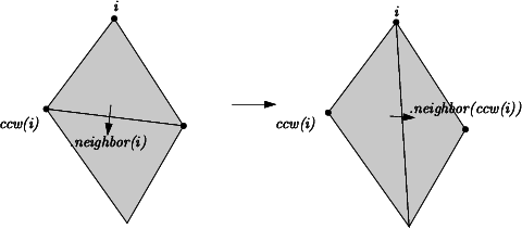
The triangulation can be modified by several functions: insertion of a point, removal of a vertex, displacement of a vertex, flipping of an edge. The flipping of an edge is possible when the union of the two incident faces forms a convex quadrilateral (see Figure 39.5).
Locate is implemented by a stochastic walk [3]. The walk begins at a vertex of the face which is given as an optional argument or at an arbitrary vertex of the triangulation if no optional argument is given. It takes time \( O(n)\) in the worst case for Delaunay Triangulations, but only \( O(\sqrt{n})\) on average if the vertices are distributed uniformly at random. The class Triangulation_hierarchy_2<Traits,Tds>, described in section The Triangulation Hierarchy, implements a data structure designed to offer an alternate more efficient point location algorithm.
Insertion of a point is done by locating a face that contains the point, and splitting this face into three new faces. If the point falls outside the convex hull, the triangulation is restored by flips. Apart from the location, insertion takes a time \( O(1)\). This bound is only an amortized bound for points located outside the convex hull.
Removal of a vertex is done by removing all adjacent triangles, and re-triangulating the hole. Removal takes a time at most proportional to \( d^2\), where \( d\) is the degree of the removed vertex, which is \( O(1)\) for a random vertex.
Displacement of a vertex is done by: first, verifying if the triangulation embedding remains planar after the displacement; if yes the vertex is directly placed at the new location; otherwise, a point is inserted at the new location and the vertex at the obsolete location is removed.
The face, edge, and vertex iterators on finite features are derived from their counterparts visiting all (finite and infinite) features which are themselves derived from the corresponding iterators of the triangulation data structure.
The geometric traits class of a triangulation is required to provide the geometric objects (points, segments and triangles) building up the triangulation together with the geometric predicates on those objects. The required predicates are:
x or y coordinates of two points.The concept TriangulationTraits_2 describes the requirements for the geometric traits class of a triangulation. The CGAL kernel classes are models for this concept. The CGAL library also provides dedicated models of TriangulationTraits_2 using the kernel geometric objects and predicates. These classes are themselves templated with a CGAL kernel and extract the required types and predicates from the kernel. The class Projection_traits_xy_3<R> is a geometric traits class to build the triangulation of a terrain. Such a triangulation is a two-dimensional triangulation embedded in three dimensional space. The data points are three-dimensional points. The triangulation is build according to the projections of those points on the \( xy\) plane and then lifted up to the original three-dimensional data points. This is especially useful to deal with GIS terrains. Instead of really projecting the three-dimensional points and maintaining a mapping between each point and its projection (which costs space and is error prone), the traits class supplies geometric predicates that ignore the z-coordinates of the points. See Section Delaunay Triangulations for an example. CGAL provides also the geometric traits classes Projection_traits_yz_3<R> and Projection_traits_xz_3<R> to deal with projections on the yz plane and xz-plane, respectively.
The following program creates a triangulation of 2D points using the default kernel Exact_predicate_inexact_constructions_kernel as geometric traits class and the default triangulation data structure. The input points are read from a file and inserted in the triangulation. Finally points on the convex hull are written to cout.
File Triangulation_2/triangulation_prog1.cpp
A 2D triangulation can be visualized by calling the CGAL::draw() function as shown in the following example. This function opens a new window showing the given 2D triangulation. The function is blocking, that is the program continues as soon as the user closes the window.
File Triangulation_2/draw_triangulation_2.cpp
This function requires CGAL_Qt5, and is only available if the flag CGAL_USE_BASIC_VIEWER is defined at compile time.
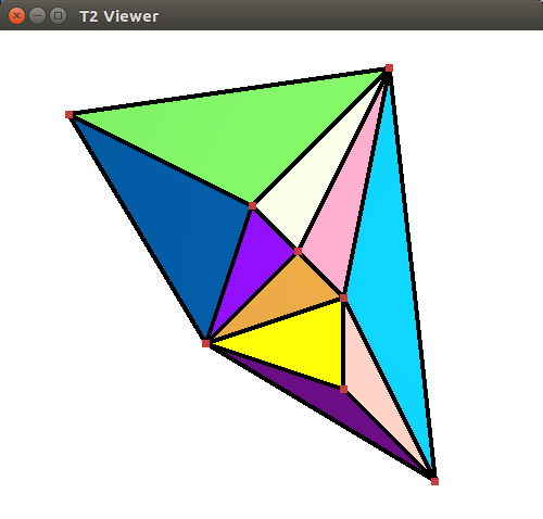
The class Delaunay_triangulation_2<Traits,Tds> is designed to represent the Delaunay triangulation of a set of data points in the plane. A Delaunay triangulation fulfills the following empty circle property (also called Delaunay property): the circumscribing circle of any facet of the triangulation contains no data point in its interior. For a point set with no subset of four co-circular points the Delaunay triangulation is unique, it is dual to the Voronoi diagram of the set of points.
The class Delaunay_triangulation_2<Traits,Tds> derives from the class Triangulation_2<Traits,Tds>.
The class Delaunay_triangulation_2<Traits,Tds> inherits the types defined by the basic class Triangulation_2<Traits,Tds>. Additional types, provided by the traits class, are defined to represent the dual Voronoi diagram.
The class Delaunay_triangulation_2<Traits,Tds> overwrites the member functions that insert, move, or remove a point in the triangulation to maintain the Delaunay property. It also has a member function (Vertex_handle Delaunay_triangulation_2::nearest_vertex(const Point& p)) to answer nearest neighbor queries and member functions to construct the elements (vertices and edges) of the dual Voronoi diagram.
The geometric traits class has to be a model of the concept DelaunayTriangulationTraits_2 which refines the concept TriangulationTraits_2. In particular this concept provides the side_of_oriented_circle predicate which, given four points p,q,r,s decides the position of the point \( s\) with respect to the circle passing through \( p\), \( q\) and \( r\). The side_of_oriented_circle predicate actually defines the Delaunay triangulation. Changing this predicate allows the user to build variant of Delaunay triangulations for different metrics such that \( L_1\) or \( L_{\infty}\) metric or any metric defined by a convex object. However, the user of an exotic metric must be careful that the constructed triangulation has to be a triangulation of the convex hull which means that convex hull edges have to be Delaunay edges. This is granted for any smooth convex metric (like \( L_2\)) and can be ensured for other metrics (like \( L_{\infty}\)) by the addition to the point set of well chosen sentinel points.
The CGAL kernel classes are models of the concept DelaunayTriangulationTraits_2 for the Euclidean metric. The traits class for terrains, Projection_traits_xy_3<R>, Projection_traits_yz_3<R>, and Projection_traits_xz_3<R> are also models of DelaunayTriangulationTraits_2 except that they do not fulfill the requirements for the duality functions and nearest vertex queries.
The insertion of a new point in the Delaunay triangulation is performed using first the insertion member function of the basic triangulation and second performing a sequence of flips to restore the Delaunay property. The number of flips that have to be performed is \( O(d)\) if the new vertex has degree \( d\) in the updated Delaunay triangulation. For points distributed uniformly at random, each insertion takes time \( O(1)\) on average, once the point has been located in the triangulation.
Removal calls the removal in the triangulation and then re-triangulates the hole created in such a way that the Delaunay criterion is satisfied. Removal of a vertex of degree \( d\) takes time \( O(d^2)\). The degree \( d\) is \( O(1)\) for a random vertex in the triangulation. When the degree of the removed vertex is small ( \( \leq7\)) a special procedure is used that allows to decrease global removal time by a factor of 2 for random points [5].
The displacement of a vertex \( v\) at a point \( p\) to a new location \( p'\), first checks whether the triangulation embedding remains planar or not after moving \( v\) to \( p'\). If yes, it moves \( v\) to \( p'\) and simply performs a sequence of flips to restore the Delaunay property, which is \( O(d)\) where \( d\) is the degree of the vertex after the displacement. Otherwise, the displacement is done by inserting a vertex at the new location, and removing the obsolete vertex. The complexity is \( O(n)\) in the worst case, but only \( O(1 + \delta \sqrt{n})\) for evenly distributed vertices in the unit square, where \( \delta\) is the Euclidean distance between the new and old locations.
After having performed a point location, the nearest neighbor of a point is found in time \( O(n)\) in the worst case, but in time \( O(1)\) for vertices distributed uniformly at random and any query point.
The following code creates a Delaunay triangulation with the usual Euclidean metric for the vertical projection of a terrain model. The points have elevation, that is they are 3D points, but the predicates used to build the Delaunay triangulation are computed using only the \( x\) and \( y\) coordinates of these points.
The class Projection_traits_xy_3<K> is part of the 2D and 3D Linear Geometric Kernel.
File Triangulation_2/terrain.cpp
The following code computes the edges of Voronoi diagram of a set of data points and counts the number of finite edges and the number of rays of this diagram
File Triangulation_2/voronoi.cpp
The following code computes the Delaunay triangulation of a set of points and prints the Voronoi edges restricted to a given rectangle.
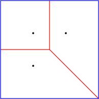
File Triangulation_2/print_cropped_voronoi.cpp
Let \( { PW} = \{(p_i, w_i) | i = 1, \ldots , n \}\) be a set of weighted points where each \( p_i\) is a point and each \( w_i\) is a scalar called the weight of point \( p_i\). Alternatively, each weighted point \( (p_i, w_i)\) can be regarded as a sphere (or a circle, depending on the dimensionality of \( p_i\)) with center \( p_i\) and radius \( r_i=\sqrt{w_i}\).
The power diagram of the set \( { PW}\) is a space partition in which each cell corresponds to a sphere \( (p_i, w_i)\) of \( { PW}\) and is the locus of points \( p\) whose power with respect to \( (p_i, w_i)\) is less than its power with respect to any other sphere in \( { PW}\). In the two-dimensional space, the dual of this diagram is a triangulation whose domain covers the convex hull of the set \( { P}= \{ p_i | i = 1, \ldots , n \}\) of center points and whose vertices form a subset of \( { P}\). Such a triangulation is called a regular triangulation. Three points \( p_i, p_j\) and \( p_k\) of \( { P}\) form a triangle in the regular triangulation of \( { PW}\) iff there is a point \( p\) of the plane with equal powers with respect to \( (p_i, w_i)\), \( (p_j, w_j)\) and \( (p_k, w_k)\) and such that this power is less than the power of \( p\) with respect to any other sphere in \( { PW}\).
Let us defined the power product of two weighted points \( (p_i, w_i)\) and \( (p_j, w_j)\) as:
\[ \Pi(p_i, w_i, p_j, w_j) = p_ip_j ^2 - w_i - w_j . \]
\( \Pi(p_i, w_i, p_j, 0)\) is simply the power of point \( p_j\) with respect to the sphere \( (p_i, w_i)\), and two weighted points are said to be orthogonal if their power product is null. The power circle of three weighted points \( (p_i, w_i)\), \( (p_j, w_j)\) and \( (p_k, w_k)\) is defined as the unique circle \( (\pi, \omega)\) orthogonal to \( (p_i, w_i)\), \( (p_j, w_j)\) and \( (p_k, w_k)\).
The regular triangulation of the sets \( { PW}\) satisfies the following regular property (which just reduces to the Delaunay property when all the weights are null): a triangle \( p_ip_jp_k\) is a face of the regular triangulation of \( { PW}\) iff the power product of any weighted point \( (p_l, w_l)\) of \( { PW}\) with the power circle of \( (p_i, w_i)\), \( (p_j, w_j)\) and \( (p_k, w_k)\) is positive or null. We call power test of \( (p_i, w_i)\), \( (p_j, w_j)\), \( (p_k, w_k)\), and \( (p_l, w_l)\), the predicates which amount to compute the sign of the power product of \( (p_l, w_l)\) with respect to the power circle of \( (p_i, w_i)\), \( (p_j, w_j)\) and \( (p_k, w_k)\). This predicate amounts to computing the sign of the following determinant
\[ \left| \begin{array}{cccc} 1 & x_i & y_i & x_i ^2 + y_i ^2 - w_i \\ 1 & x_j & y_j & x_j ^2 + y_j ^2 - w_j \\ 1 & x_k & y_k & x_k ^2 + y_k ^2 - w_k \\ 1 & x_l & y_l & x_l ^2 + y_l ^2 - w_l \end{array} \right| \]
A pair of neighboring faces \( p_ip_jp_k\) and \( p_ip_jp_l\) is said to be locally regular (with respect to the weights in \( { PW}\)) if the power test of \( (p_i, w_i)\), \( (p_j, w_j)\), \( (p_k, w_k)\), and \( (p_l, w_l)\) is positive. A classical result of computational geometry establishes that a triangulation of the convex hull of \( { P}\) such that any pair of neighboring faces is regular with respect to \( { PW}\), is a regular triangulation of \( { PW}\).
Alternatively, the regular triangulation of the weighted points set \( { PW}\) can be obtained as the projection on the two dimensional plane of the convex hull of the set of three dimensional points \( { P'}= \{ (p_i,p_i ^2 - w_i ) | i = 1, \ldots , n \}\).
The class Regular_triangulation_2<Traits, Tds> is designed to maintain the regular triangulation of a set of \( 2d\) weighted points. It derives from the class Triangulation_2<Traits, Tds>. The functions insert and remove are overwritten to handle weighted points and maintain the regular property. The function move() is not overwritten and thus does not preserve the regular property. The vertices of the regular triangulation of a set of weighted points \( {PW}\) correspond only to a subset of \( {PW}\). Some of the input weighted points have no cell in the dual power diagrams and therefore do not correspond to a vertex of the regular triangulation. Such a point is called a hidden point. Because hidden points can reappear later on as vertices when some other point is removed, they have to be stored somewhere. The regular triangulation store those points in special vertices, called hidden vertices. A hidden point can reappear as vertex of the triangulation only when the two dimensional face that hides it is removed from the triangulation. To deal with this feature, each face of a regular triangulation stores a list of hidden vertices. The points in those vertices are reinserted in the triangulation when the face is removed.
Regular triangulation have member functions to construct the vertices and edges of the dual power diagrams.
The geometric traits class of a regular triangulation must provide a weighted point type and a power test on these weighted points. The concept RegularTriangulationTraits_2, is a refinement of the concept TriangulationTraits_2. All CGAL kernels are a model for the traits concept RegularTriangulationTraits_2.
The base vertex type of a regular triangulation includes a Boolean data member to mark the hidden state of the vertex. Therefore CGAL defines the concept RegularTriangulationVertexBase_2 which refine the concept TriangulationVertexBase_2 and provides a default model for this concept.
The face base type of a regular triangulation is required to provide a list of hidden vertices, designed to store the points hidden by the face. It has to be a model of the concept RegularTriangulationFaceBase_2. CGAL provides the templated class Regular_triangulation_face_base_2<Traits> as a default base class for faces of regular triangulations.
The following code creates a regular triangulation of a set of weighted points and output the number of vertices and the number of hidden vertices.
File Triangulation_2/regular.cpp
A constrained triangulation is a triangulation of a set of points that has to include among its edges a given set of polylines joining the points. The polylines are called constraints. The corresponding edges are called constrained edges.
The endpoints of constrained edges are of course vertices of the triangulation. However, the triangulation may include other vertices as well. There are three versions of constrained triangulations.

A constrained triangulation is represented in the CGAL library as an object of the class Constrained_triangulation_2<Traits,Tds,Itag>. The third parameter Itag is the intersection tag which serves to choose how intersecting constraints are dealt with. This parameter has to be instantiated by one of the following classes:
No_intersection_tag when input constraints do not intersectExact_predicates_tag if the geometric traits class provides exact predicates but approximate constructionsExact_intersections_tag when exact predicates and exact constructions are provided.The class Constrained_triangulation_2<Traits,Tds, Itag> inherits from Triangulation_2<Traits,Tds>. A constrained triangulation can be created from a list of pairs of points which represent the constraints.
The class Constrained_triangulation_2<Traits,Tds,Itag> overrides the insertion and removal of a point to take care of the information about constrained edges. The class also allows the user online insertion of a new constraint, given as sequence of points, or the removal of a constraint. In the current version, the function move() is not overwritten and thus does not handle vertices of constraints.
In order to retrieve the constrained edges of a constraint, or the constraints overlapping with a constrained edge, we provide the class Constrained_triangulation_plus_2. See Section Constrained Triangulations with a Bidirectional Mapping between Constraints and Subconstraints for details. This class should also be used when doing exact intersection computations as it avoids the cascading of intersection computations.
The geometric traits class of a constraint triangulation has to be a model of the concept TriangulationTraits_2. When intersections of input constraints are supported, the geometric traits class has to be a model of the concept ConstrainedTriangulationTraits_2, which refines the concept TriangulationTraits_2 providing additional function object types to compute the intersection of two segments.
The information about constrained edges is stored in the faces of the triangulation. The face base of a Constrained Triangulation has to be a model for the concept ConstrainedTriangulationFaceBase_2 which refines the concept TriangulationFaceBase_2. The concept ConstrainedTriangulationFaceBase_2 requires member functions that get and set the constrained status of the edges.
CGAL provides a default face base class for constrained triangulations. This class, named Constrained_triangulation_face_base_2<Traits>, derives from the class Triangulation_face_base_2<Traits> and adds three Boolean data members to store the status of its edges.
A constrained Delaunay triangulation is a triangulation with constrained edges which try to be as much Delaunay as possible. As constrained edges are not necessarily Delaunay edges, the triangles of a constrained Delaunay triangulation do not necessarily fulfill the empty circle property but they fulfill a weaker constrained empty circle property. To state this property, it is convenient to think of constrained edges as blocking the view. Then, a triangulation is constrained Delaunay iff the circumscribing circle of any facet encloses no vertex visible from the interior of the facet. As in the case of constrained triangulations, three different versions of Delaunay constrained triangulations are provided. The first version handles a set of constraints which do not intersect except possibly at the endpoints. The two other versions handle intersecting input constraints. One of them is designed to be robust when used in conjunction with a geometric traits class providing exact predicates and approximate constructions (such as a Filtered_kernel or any kernel providing filtered exact predicates). The third version is designed to be used with an exact arithmetic number type.
The CGAL class Constrained_Delaunay_triangulation_2<Traits,Tds,Itag> is designed to represent constrained Delaunay triangulations.
As in the case of constrained triangulations, the third parameter Itag is the intersection tag and serves to choose how intersecting constraints are dealt with. It can be instantiated with one of the following classes: No_intersection_tag, Exact_predicates_tag, Exact_intersections_tag (see Section Constrained Triangulations).
A constrained Delaunay triangulation is not a Delaunay triangulation but it is a constrained triangulation. Therefore the class Constrained_Delaunay_triangulation_2<Traits,Tds,Itag> derives from the class Constrained_triangulation_2<Traits,Tds,Itag>.
The constrained Delaunay triangulation has member functions to override the insertion and removal of a point or of a constraint. Each of those member functions takes care to restore the constrained empty circle property.
The geometric traits class of a constrained Delaunay triangulation is required to provide the side_of_oriented_circle predicate as the geometric traits class of a Delaunay triangulation, and has to be a model of the concept DelaunayTriangulationTraits_2. When intersecting input constraints is supported, the geometric traits class is further required to provide function objects to compute constraints intersections. Then, the geometric traits class has to be at the same time a model of the concept ConstrainedTriangulationTraits_2.
Information about the status (constrained or not) of the edges of the triangulation has to be stored in the face class, and the face base class of a constrained Delaunay triangulation has to be a model of ConstrainedTriangulationFaceBase_2.
The following code inserts a set of intersecting constraint segments into a triangulation and counts the number of constrained edges of the resulting triangulation.
File Triangulation_2/constrained.cpp
The following code inserts two nested polygons into a constrained Delaunay triangulation and counts the number of facets that are inside the domain delimited by these polygons. Note that the following code does not work if the boundaries of the polygons intersect.
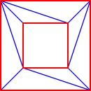
File Triangulation_2/polygon_triangulation.cpp
The class Constrained_triangulation_plus_2<Tr> provides a constrained triangulation with an additional data structure that keeps track of the input constraints and of their refinement in the triangulation. The class Constrained_triangulation_plus_2<Tr> inherits from its template parameter Tr, which has to be instantiated by a constrained or constrained Delaunay triangulation. According to its intersection tag, the base class will support intersecting input constraints or not. When intersections of input constraints are supported, the base class constructs a triangulation of the arrangement of the constraints, introducing new vertices at each proper intersection point.
The triangulation maintains for each input constraint the sequence of vertices on this constraint. These vertices are either vertices of the input constraint or intersection points.
Two consecutive vertices of an input constraint form a subconstraint. The triangulation enables the retrieval of the set of subconstraints of the triangulation (not ordered along constraints).
It further enables the retrieval of the set of input constraints that induce a subconstraint. As it is straightforward to obtain a subconstraint from a constrained edge e, one can easily obtain the input constraints that induce e.
All triangulation classes define the type Edge as typedef std::pair<Face_handle, int> Edge. For a pair (fh,i) it is the edge of the face *fh, which is opposite to the i'th vertex.
A constrained edge e is an edge of a constrained triangulation ct, for which ct.is_constrained(e) returns true.
A constraint is a polyline which is given as input (in the simplest case just a segment), and which is split into constrained edges in the triangulation.
The type Subconstraint is defined as typedef std::pair<Vertex_handle,Vertex_handle> Subconstraint. The two vertex handles must be the vertices of a constrained edge.
The type Constraint_id identifies a constraint.
All constrained triangulation classes of CGAL provide functions to insert constraints, have the notion of constrained edges, and offer a Constrained_edges_iterator.
The class Constrained_triangulation_plus_2 additionally provides the means to
Constraint_iterator the value type of which is Constraint_id,Vertices_in_constraint_iterator, the value type of which is Vertex_handleSubconstraint_iterator,the value type of which is Subconstraint.Note that the Constrained_edges_iterator and the Subconstraint_iterator are quite similar. The Constrained_edges_iterator traverses all edges and skips those that are not constrained, which means that the time of traversal will be linear in the number of total edges. whereas the Subconstraint_iterator traverses a set of subconstraints stored in the triangulation.
On the other hand, as a subconstraint is only a pair of vertex handles, determining the corresponding Edge takes the smaller degree of the two vertices, wheresas obtaining an Edge from a subconstraint is a constant time operation.
The class Constrained_triangulation_plus_2<Tr> is especially useful when the base constrained triangulation class handles intersections of constraints and uses an exact number type, i.e. when its intersection tag is Exact_intersections_tag. In this case, the Constrained_triangulation_plus_2<Tr> avoids cascading in the computations of intersection points.
This is best explained with an example.
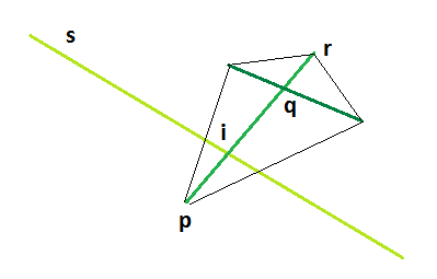
When inserting a constraint, say a segment s in the triangulation, this segment may intersect a constrained edge e with the vertices p and q. The algorithm could compute the intersection point i of s with the segment [p,q]. Because these points may be previously constructed intersection points, as q in the figure above, it is better to use an input constraint c that induce the edge. If c is a segment, the algorithm intersects s with c. If c is a polyline, the algorithm finds two vertices from the input constraint that define an input segment that induce e.
The following code inserts two polyline constraints into a triangulation. Note that if the triangulation supports intersections we can have arbitrary complicated overlapping polylines. They can share any number of edges, and a polyline may pass several times through the same edge.
For an edge we can further find out how many and which polyline constraints pass through it. For an edge we can obtain an iterator range with value type Constrained_triangulation_plus_2::Context. From a context we can obtain the Constrained_triangulation_plus_2::Constraint_id, and an iterator pointing at the vertex in the polyline constraint that passes through the edge.
File Triangulation_2/polylines_triangulation.cpp
The class Triangulation_hierarchy_2<Tr> implements a triangulation augmented with a data structure to efficiently answer point location queries. The data structure is a hierarchy of triangulations. The triangulation at the lowest level is the original triangulation where operations and point location are to be performed. Then at each succeeding level, the data structure stores a triangulation of a small random sample of the vertices of the triangulation at the preceding level. Point location is done through a top down nearest neighbor query. The nearest neighbor query is first performed naively in the top level triangulation. Then, at each following level, the nearest neighbor at that level is found through a linear walk performed from the nearest neighbor found at the preceding level. Because the number of vertices in each triangulation is only a small fraction of the number of vertices of the preceding triangulation, the data structure remains small and achieves fast point location queries on real data. As proved in [4], this structure has an optimal behavior when it is built for Delaunay triangulations. However, it can be used as well for other triangulations and the class Triangulation_hierarchy_2<Tr> is templated by a parameter which is to be instantiated by one of the CGAL triangulation classes.
The class Triangulation_hierarchy_2<Tr> inherits from the triangulation type passed as template parameter Tr. The insert, move, and remove member functions are overwritten to update the data structure at each operation. The locate queries are also overwritten to take advantage of the data structure for a fast processing.
The base vertex class of a triangulation hierarchy has to be a model of the concept TriangulationHierarchyVertexBase_2 which extends the concept TriangulationVertexBase_2. This extension adds access and setting member functions for two pointers to the corresponding vertices in the triangulations of the next and preceding levels.
CGAL provides the class Triangulation_hierarchy_vertex_base_2<Vb> which is a model for the concept TriangulationHierarchyVertexBase_2. This class is templated by a parameter Vb which is to be instantiated by a model of the concept TriangulationVertexBase_2. The class Triangulation_hierarchy_vertex_base_2<Vb> inherits from its template parameter Vb. This design enables the usage of either the default vertex class or a user customized vertex class with additional functionalities for Vb.
The following program is an example for the standard use of a triangulation hierarchy to enhance the efficiency of a Delaunay triangulation. The program outputs the number of vertices at the different levels of the hierarchy.
File Triangulation_2/hierarchy.cpp
The following program shows how to use a triangulation hierarchy in conjunction with a constrained triangulation with a constaint hierarchy.
File Triangulation_2/constrained_hierarchy_plus.cpp
To be able to adapt to various needs, a highly flexible design has been selected for 2D triangulations. We have already seen that the triangulation classes have two parameters: a geometric traits class and a triangulation data structure class which the user can instantiate with his own customized classes.
The most useful flexibility however comes from the fact that the triangulation data structure itself has two template parameters to be instantiated by classes for the vertices and faces of the triangulation. Using his own customized classes to instantiate these parameters, the user can easily build up a triangulation with additional information or functionality in the vertices and faces.
To insure flexibility, the triangulation data structure is templated by the vertex and face base classes. Also since incidence and adjacency relations are stored in vertices and faces, the base classes have to know the types of handles on vertices and faces provided by the triangulation data structure. Thus the vertex and face base classes have to be themselves parameterized by the triangulation data structure, and there is a cyclic dependency on template parameter.
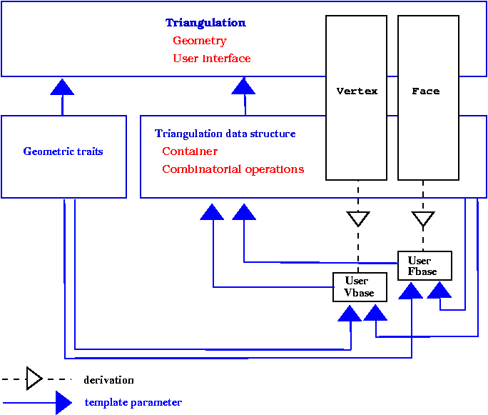
Previously, this cyclic dependency was avoided by using only void* pointers in the interface of base classes. These void* were converted to appropriate types at the triangulation data structure levels. This solution had some drawbacks : mainly the user could not add in the vertices or faces of the triangulation a functionality related to types defined by the triangulation data structure, for instance a handle to a vertex, and he was lead to use himself void* pointers). The new solution to resolve the template dependency is based on a rebind mechanism similar to the mechanism used in the standard allocator class std::allocator. The rebind mechanism is described in Section The Default Triangulation Data Structure of Chapter 2D Triangulation Data Structure. For now, we will just notice that the design requires the existence in the vertex and face base classes of a nested template class Rebind_TDS defining a type Other used by the rebinding mechanism.
The two following examples show how the user can put in use the flexibility offered by the base classes parameters.
The first example corresponds to a case where the user wishes to add in the vertices or faces of the triangulation an additional information that does not depend on types provided by the triangulation data structure. In that case, predefined classes Triangulation_vertex_base_with_info_2<Info,Traits,Vb> or Triangulation_face_base_with_info_2<Info,Traits,Vb> can be used. Those classes have a template parameter Info devoted to handle additional information. The following example shows how to add a Color in the triangulation faces.
File Triangulation_2/colored_face.cpp
The second example adds a std::string in the vertices of a terrain.
File Triangulation_2/terrain_with_info.cpp
This example shows how the user can still derive and plug in his own vertex or face class when he would like to have additional functionalities depending on types provided by the triangulation data structure.
File Triangulation_2/adding_handles.cpp
The most efficient method to insert (weighted) points in a Delaunay (or regular) triangulation is to provide an iterator range over (weighted) points to the insert function. However, an iterator range of (weighted) points does not allow the user to set different information to each vertex. To solve this problem, in the case the vertex type of the triangulation is a model of the concept TriangulationVertexBaseWithInfo_2 (such as Triangulation_vertex_base_with_info_2), we provide three examples doing the same operation: set an unsigned integer as the information of each vertex. The value of this unsigned integer is the initial order of the corresponding point given in the range.
Each point and its information are gathered into a pair. We provide the insert function of the triangulation with a range of such pairs.
File Triangulation_2/info_insert_with_pair_iterator_2.cpp
Information and points are in separate containers. We use boost::zip_iterator to provide an iterator gathering them.
File Triangulation_2/info_insert_with_zip_iterator_2.cpp
We define a functor Auto_count used together with boost::transform_iterator to set the order of each point in the range. Note that this is correct because the iterator is dereferenced only once per point during the insertion.
File Triangulation_2/info_insert_with_transform_iterator_2.cpp
The code of this package is the result of a long development process. Here follows a tentative list of people who added their stone to this package: Jean-Daniel Boissonnat, Hervé Brönnimann, Olivier Devillers, Andreas Fabri, Frédéric Fichel, Julia Flötotto, Monique Teillaud and Mariette Yvinec.