CGAL 5.1 - Triangulated Surface Mesh Deformation
User Manual

Authors
Sébastien Loriot, Olga Sorkine-Hornung, Yin Xu and Ilker O. Yaz
main_image_suggestion_4_resized.png

Introduction

This package offers surface mesh deformation algorithms which compute new vertex positions of a surface mesh under positional constraints of some of its vertices, without requiring any additional structure other than the surface mesh itself

This package implements the algorithm described in [6] together with an alternative energy function [3]. The algorithm minimizes a nonlinear deformation energy under positional constraints to preserve rigidity as much as possible. The minimization of the energy relies on solving sparse linear systems and finding closest rotation matrices.

Definitions

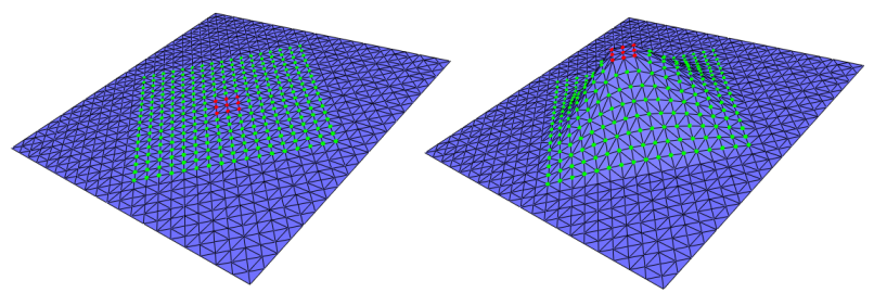
A surface mesh deformation system consists of:

  • a triangulated surface mesh (surface mesh in the following),
  • a set of vertices defining the region to deform (referred to as the region-of-interest and abbreviated ROI),
  • a subset of vertices from the ROI that the user wants to move (referred to as the control vertices),
  • a target position for each control vertex (defining the deformation constraints).

A vertex from the ROI that is not a control vertex is called an unconstrained vertex. These definitions are depicted in Figure 69.1.

roi_example.png
Figure 69.1 The ROI features the green vertices (the unconstrained vertices) and the red vertices (the control vertices). (Left) The initial surface mesh; (Right) A target position is defined for each control vertex, the coordinates of the unconstrained vertices being updated by the deformation algorithm.

In this package, three algorithms are implemented:

  • The As-Rigid-As-Possible (ARAP) method [6];
  • The Spokes and Rims method [3];
  • The Smoothed Rotation Enhanced As-Rigid-As-Possible method [4]

Given an edge weighting scheme, both methods iteratively minimize an energy function and produce a different surface mesh at each step until convergence is reached.

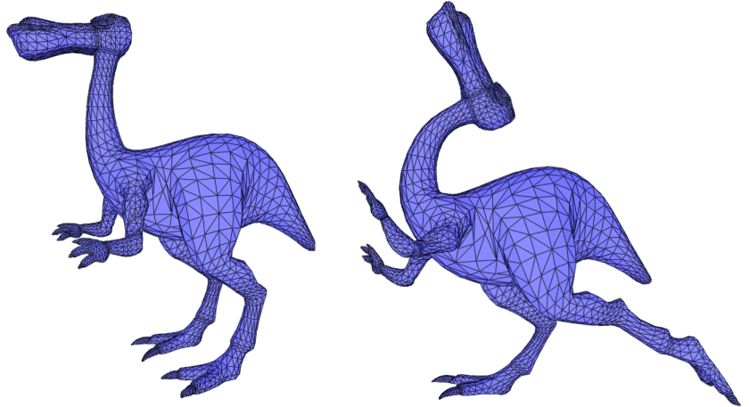
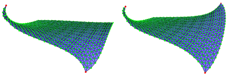
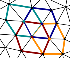
Spokes and Rims is the default method proposed by the package. It provides an unconditional convergence while the ARAP method requires the edge weights to be positive. However, the results obtained using the Spokes and Rims method are more dependent on the discretization of the deformed surface (See Figure 69.2).

The Smoothed Rotation Enhanced As-Rigid-As-Possible method adds a bending term to the ARAP energy that penalizes rotation difference between neighboring elements. In the current implementation a 1-ring type element is used while in general it is possible to use a triangle type element.

More details on these algorithms are provided in section Deformation Techniques, Energies and Weighting Schemes.

arap_spokes_comparison.png
Figure 69.2 A comparison between the As-Rigid-As-Possible and the Spokes and Rims deformation methods. On the surface mesh of a square with spikes depicted on the left, the ROI consists of the green vertices. The control vertices are the red ones. We translate the control vertices along the normal to the plane and observe the result produced by the As-Rigid-As-Possible (center) and the Spokes and Rims (right) methods from the same view point. The latter method provides unconditional convergence does not produce a symmetric result.

sr_arap_comparison.png
Figure 69.3 A comparison on a 5261 vertices cactus model (left) between the As-Rigid-As-Possible (middle) and the Smoothed Rotation Enhanced As-Rigid-As-Possible (right).

User Interface Description

The deformation methods implemented rely on solving a sparse linear system. The sparse matrix definition depends on the weighting scheme and on the unconstrained and control vertices. The right term depends only on the target positions of the control vertices.

The deformation process is handled by the class Surface_mesh_deformation and the surface mesh is represented as a halfedge data structure that must be a model of the HalfedgeGraph concept.

The class Surface_mesh_deformation provides two groups of functions for the preprocessing (sparse matrix definition) and the deformation (right hand term definition).

Preprocessing

The preprocessing consists in computing a factorization of the aforementioned sparse matrix to speed up the linear system resolution. It requires the ROI to be defined. The following conventions are used for the definition of the ROI:

  • A vertex inserted in the set of control vertices is inserted in the ROI;
  • A control vertex erased from the ROI is no longer considered as a control vertex;
  • A control vertex that is erased is not erased from the ROI.

Each time the ROI is modified, the preprocessing function preprocess() must be called. Note that if it is not done, the first deformation step calls this function automatically and has a longer runtime compared to subsequent deformation steps.

The function Surface_mesh_deformation::preprocess() returns true if the factorization is successful, and false otherwise.

Rank deficiency is the main reason for failure. Typical failure cases are:

  • All the vertices are in the ROI and no control vertices are set
  • The weighting scheme used to fill the sparse matrix (model of SurfaceMeshDeformationWeights) features too many zeros and breaks the connectivity information

Advanced

The choice of the weighting scheme provides a mean to adjust the way the control vertices influences the unconstrained vertices. The defaults provides satisfactory results in general but other weighting schemes may be selected or designed to experiment or improve the results in specific cases.

Note
The ROI does not have to be a connected component of the graph of the surface mesh. However, for better performances it is better to use an individual instance of the deformation object for each connected component.

Deformation

The deformation of the surface mesh is triggered by the displacement of the control vertices. This is achieved through setting the target positions of the control vertices (directly or by using an affine transformation to be applied to a control vertex or a range of control vertices).

Note that a rotation or a translation of a control vertex is always applied on its last target position set: they are cumulative.

The deformation of the surface mesh happens when calling the function Surface_mesh_deformation::deform(). The number of optimization iterations varies depending on whether the user chooses a fixed number of iterations or a stopping criterion based on the energy variation.

After the call to the deformation function, the input surface mesh is updated and the control vertices are at their target positions and the unconstrained vertices are moved accordingly. The function Surface_mesh_deformation::deform() can be called several times consecutively, in particular if the convergence has not been reached yet (otherwise it has no effect).

Warning
Vertices can be inserted into or erased from the ROI and the set of control vertices at any time. In particular, any vertex that is no longer inside the ROI will be assigned to its original position when Surface_mesh_deformation::preprocess() is first called. The original positions can be updated by calling Surface_mesh_deformation::overwrite_initial_geometry() ( which will also require a new preprocessing step). This behavior is illustrated in Video 1.

As-Rigid-As-Possible and Spokes-and-Rims Deformation Techniques

Three deformation techniques are provided by this package. This section summarizes from the user point of view what is explained in details in the section Deformation Techniques, Energies and Weighting Schemes.

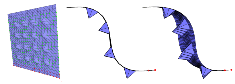
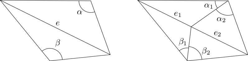
The As-Rigid-As-Possible deformation techniques require the use of a positive weighting scheme to guarantee the correct minimization of the energy. When using the default cotangent weighting scheme, this means that the input surface mesh must be clean. That is, that for all edges in the surface mesh the sum of the angles opposite to the edge in the incident triangles is less that \( \pi \). If this is not the case and the targeted application allows the modification of the surface mesh connectivity, a solution (amongst other) is to bissect (possibly recursively) the problematic edges. See Figure 69.4.

cotangent_bisect.png
Figure 69.4 Cotangent weight of edges. (Left) The sum of the opposite angles to the edge \( e \), \( \alpha + \beta \) is greater than \( \pi \). The cotangent weight of \( e \) is negative. (Right) The edge \( e \) was split so that the sum of the angles opposite to each sub-edge \( e_1 \) and \( e_2 \) is less than \( \pi \). The corresponding cotangent weights are positive.

If the mesh connectivity must be preserved, the Spokes and Rims deformation technique is guaranteed to always correctly minimize the energy even if the weights are negative. However, this technique is more dependent on the discretization of the deformed surface (See Figure 69.2).

Examples

Using the Whole Surface Mesh as Region-of-Interest

In this example, the whole surface mesh is used as ROI and a few vertices are added as control vertices. Surface_mesh_deformation::set_target_position() is used for setting the target positions of the control vertices.


File Surface_mesh_deformation/all_roi_assign_example.cpp

#include <CGAL/Simple_cartesian.h>
#include <CGAL/Polyhedron_3.h>
#include <CGAL/Polyhedron_items_with_id_3.h>
#include <CGAL/Surface_mesh_deformation.h>
#include <fstream>
typedef boost::graph_traits<Polyhedron>::vertex_descriptor vertex_descriptor;
typedef boost::graph_traits<Polyhedron>::vertex_iterator vertex_iterator;
typedef CGAL::Surface_mesh_deformation<Polyhedron> Surface_mesh_deformation;
int main()
{
Polyhedron mesh;
std::ifstream input("data/plane.off");
if ( !input || !(input >> mesh) || mesh.empty() ) {
std::cerr<< "Cannot open data/plane.off" << std::endl;
return 1;
}
// Init the indices of the halfedges and the vertices.
// Create a deformation object
Surface_mesh_deformation deform_mesh(mesh);
// Definition of the region of interest (use the whole mesh)
vertex_iterator vb,ve;
boost::tie(vb, ve) = vertices(mesh);
deform_mesh.insert_roi_vertices(vb, ve);
// Select two control vertices ...
vertex_descriptor control_1 = *std::next(vb, 213);
vertex_descriptor control_2 = *std::next(vb, 157);
// ... and insert them
deform_mesh.insert_control_vertex(control_1);
deform_mesh.insert_control_vertex(control_2);
// The definition of the ROI and the control vertices is done, call preprocess
bool is_matrix_factorization_OK = deform_mesh.preprocess();
if(!is_matrix_factorization_OK){
std::cerr << "Error in preprocessing, check documentation of preprocess()" << std::endl;
return 1;
}
// Use set_target_position() to set the constained position
// of control_1. control_2 remains at the last assigned positions
Surface_mesh_deformation::Point constrained_pos_1(-0.35, 0.40, 0.60);
deform_mesh.set_target_position(control_1, constrained_pos_1);
// Deform the mesh, the positions of vertices of 'mesh' are updated
deform_mesh.deform();
// The function deform() can be called several times if the convergence has not been reached yet
deform_mesh.deform();
// Set the constained position of control_2
Surface_mesh_deformation::Point constrained_pos_2(0.55, -0.30, 0.70);
deform_mesh.set_target_position(control_2, constrained_pos_2);
// Call the function deform() with one-time parameters:
// iterate 10 times and do not use energy based termination criterion
deform_mesh.deform(10, 0.0);
// Save the deformed mesh into a file
std::ofstream output("deform_1.off");
output << mesh;
output.close();
// Add another control vertex which requires another call to preprocess
vertex_descriptor control_3 = *std::next(vb, 92);
deform_mesh.insert_control_vertex(control_3);
// The prepocessing step is again needed
if(!deform_mesh.preprocess()){
std::cerr << "Error in preprocessing, check documentation of preprocess()" << std::endl;
return 1;
}
// Deform the mesh
Surface_mesh_deformation::Point constrained_pos_3(0.55, 0.30, -0.70);
deform_mesh.set_target_position(control_3, constrained_pos_3);
deform_mesh.deform(15, 0.0);
output.open("deform_2.off");
output << mesh;
}

example_1_results.png
Figure 69.5 Deformation results when running example Using the Whole Surface Mesh as Region-of-Interest : deform_1.off and deform_2.off.

Using an Affine Transformation on a Range of Vertices

In this example, we use the functions translate() and rotate() on a range of control vertices. Note that the translations and the rotations are defined using a 3D vector type and a quaternion type from the Eigen library.


File Surface_mesh_deformation/k_ring_roi_translate_rotate_example.cpp

#include <CGAL/Simple_cartesian.h>
#include <CGAL/Polyhedron_3.h>
#include <CGAL/Polyhedron_items_with_id_3.h>
#include <CGAL/Surface_mesh_deformation.h>
#include <fstream>
#include <map>
#include <queue>
typedef boost::graph_traits<Polyhedron>::vertex_descriptor vertex_descriptor;
typedef boost::graph_traits<Polyhedron>::vertex_iterator vertex_iterator;
typedef boost::graph_traits<Polyhedron>::halfedge_descriptor halfedge_descriptor;
typedef boost::graph_traits<Polyhedron>::edge_descriptor edge_descriptor;
typedef Eigen::Vector3d Vector3d;
typedef CGAL::Surface_mesh_deformation<Polyhedron> Surface_mesh_deformation;
// Collect the vertices which are at distance less or equal to k
// from the vertex v in the graph of vertices connected by the edges of P
std::vector<vertex_descriptor> extract_k_ring(const Polyhedron &P, vertex_descriptor v, int k)
{
std::map<vertex_descriptor, int> D;
std::vector<vertex_descriptor> Q;
Q.push_back(v); D[v] = 0;
std::size_t current_index = 0;
int dist_v;
while( current_index < Q.size() && (dist_v = D[ Q[current_index] ]) < k ) {
v = Q[current_index++];
for(edge_descriptor e : out_edges(v, P))
{
halfedge_descriptor he = halfedge(e, P);
vertex_descriptor new_v = target(he, P);
if(D.insert(std::make_pair(new_v, dist_v + 1)).second) {
Q.push_back(new_v);
}
}
}
return Q;
}
int main()
{
Polyhedron mesh;
std::ifstream input("data/plane.off");
if ( !input || !(input >> mesh) || mesh.empty() ) {
std::cerr<< "Cannot open data/plane.off";
return 1;
}
// Init the indices of the halfedges and the vertices.
// Create the deformation object
Surface_mesh_deformation deform_mesh(mesh);
// Select and insert the vertices of the region of interest
vertex_iterator vb, ve;
boost::tie(vb,ve) = vertices(mesh);
std::vector<vertex_descriptor> roi = extract_k_ring(mesh, *std::next(vb, 47), 9);
deform_mesh.insert_roi_vertices(roi.begin(), roi.end());
// Select and insert the control vertices
std::vector<vertex_descriptor> cvertices_1 = extract_k_ring(mesh, *std::next(vb, 39), 1);
std::vector<vertex_descriptor> cvertices_2 = extract_k_ring(mesh, *std::next(vb, 97), 1);
deform_mesh.insert_control_vertices(cvertices_1.begin(), cvertices_1.end());
deform_mesh.insert_control_vertices(cvertices_2.begin(), cvertices_2.end());
// Apply a rotation to the control vertices
Eigen::Quaternion<double> quad(0.92, 0, 0, -0.38);
deform_mesh.rotate(cvertices_1.begin(), cvertices_1.end(), Vector3d(0,0,0), quad);
deform_mesh.rotate(cvertices_2.begin(), cvertices_2.end(), Vector3d(0,0,0), quad);
deform_mesh.deform();
// Save the deformed mesh
std::ofstream output("deform_1.off");
output << mesh;
output.close();
// Restore the positions of the vertices
deform_mesh.reset();
// Apply a translation on the original positions of the vertices (reset() was called before)
deform_mesh.translate(cvertices_1.begin(), cvertices_1.end(), Vector3d(0,0.3,0));
deform_mesh.translate(cvertices_2.begin(), cvertices_2.end(), Vector3d(0,0.3,0));
// Call the function deform() with one-time parameters:
// iterate 10 times and do not use energy based termination criterion
deform_mesh.set_iterations(10);
deform_mesh.set_tolerance(0.0);
deform_mesh.deform();
// Save the deformed mesh
output.open("deform_2.off");
output << mesh;
}

example_2_results.png
Figure 69.6 Deformation results when running example Using an Affine Transformation on a Range of Vertices : deform_1.off and deform_2.off.

Using Polyhedron without Ids

In the previous examples, we used an enriched polyhedron storing an ID in its halfedges and vertices together with the default property maps in the deformation object to access them. In the following example, we show how we can use alternative property maps.

For practical performance however we recommend relying upon the former examples instead, as using a std::map to access indices increases the complexity from constant to logarithmic.
File Surface_mesh_deformation/deform_polyhedron_with_custom_pmap_example.cpp

#include <CGAL/Simple_cartesian.h>
#include <CGAL/Polyhedron_3.h>
#include <CGAL/property_map.h>
#include <CGAL/Surface_mesh_deformation.h>
#include <fstream>
typedef CGAL::Polyhedron_3<Kernel> Polyhedron;
typedef boost::graph_traits<Polyhedron>::vertex_descriptor vertex_descriptor;
typedef boost::graph_traits<Polyhedron>::vertex_iterator vertex_iterator;
typedef boost::graph_traits<Polyhedron>::halfedge_descriptor halfedge_descriptor;
typedef boost::graph_traits<Polyhedron>::halfedge_iterator halfedge_iterator;
// Define the maps
typedef std::map<vertex_descriptor, std::size_t> Vertex_id_map;
typedef std::map<halfedge_descriptor, std::size_t> Hedge_id_map;
typedef boost::associative_property_map<Vertex_id_map> Vertex_id_pmap;
typedef boost::associative_property_map<Hedge_id_map> Hedge_id_pmap;
int main()
{
Polyhedron mesh;
std::ifstream input("data/plane.off");
if ( !input || !(input >> mesh) || mesh.empty() ) {
std::cerr<< "Cannot open data/plane.off";
return 1;
}
// Init the indices of the vertices from 0 to num_vertices(mesh)-1
Vertex_id_map vertex_index_map;
std::size_t counter = 0;
for(vertex_descriptor v : vertices(mesh))
vertex_index_map[v]=counter++;
// Init the indices of the halfedges from 0 to 2*num_edges(mesh)-1
Hedge_id_map hedge_index_map;
counter = 0;
for(halfedge_descriptor h : halfedges(mesh))
hedge_index_map[h]=counter++;
Surface_mesh_deformation deform_mesh( mesh,
Vertex_id_pmap(vertex_index_map),
Hedge_id_pmap(hedge_index_map) );
// Now deform mesh as desired
// .....
}

Using a Custom Edge Weighting Scheme

Using a custom weighting scheme for edges is also possible if one provides a model of SurfaceMeshDeformationWeights. In this example, the weight of each edge is pre-computed and an internal map is used for storing and accessing them.

Another example is given in the manual page of the concept SurfaceMeshDeformationWeights.


File Surface_mesh_deformation/custom_weight_for_edges_example.cpp

#include <CGAL/Simple_cartesian.h>
#include <CGAL/Polyhedron_3.h>
#include <CGAL/Surface_mesh_deformation.h>
#include <fstream>
#include <map>
#include <CGAL/property_map.h>
typedef CGAL::Polyhedron_3<Kernel> Polyhedron;
typedef boost::graph_traits<Polyhedron>::vertex_descriptor vertex_descriptor;
typedef boost::graph_traits<Polyhedron>::vertex_iterator vertex_iterator;
typedef boost::graph_traits<Polyhedron>::halfedge_descriptor halfedge_descriptor;
typedef boost::graph_traits<Polyhedron>::halfedge_iterator halfedge_iterator;
typedef std::map<vertex_descriptor, std::size_t> Internal_vertex_map;
typedef std::map<halfedge_descriptor, std::size_t> Internal_hedge_map;
typedef boost::associative_property_map<Internal_vertex_map> Vertex_index_map;
typedef boost::associative_property_map<Internal_hedge_map> Hedge_index_map;
// A model of SurfaceMeshDeformationWeights using a map of pre-computed weights
struct Weights_from_map
{
typedef Polyhedron Halfedge_graph;
Weights_from_map(std::map<halfedge_descriptor, double>* weight_map) : weight_map(weight_map)
{ }
template<class VertexPointMap>
double operator()(halfedge_descriptor e, Polyhedron& /*P*/, VertexPointMap /*vpm*/) {
return (*weight_map)[e];
}
std::map<halfedge_descriptor, double>* weight_map;
};
int main()
{
Polyhedron mesh;
std::ifstream input("data/plane.off");
if ( !input || !(input >> mesh) || mesh.empty() ) {
std::cerr << "Cannot open data/plane.off" << std::endl;
return 1;
}
std::map<halfedge_descriptor, double> weight_map;
// Store all the weights
for(halfedge_descriptor h : halfedges(mesh))
{
weight_map[h] = 1.0; // store some precomputed weights
}
// Create and initialize the vertex index map
Internal_vertex_map internal_vertex_index_map;
Vertex_index_map vertex_index_map(internal_vertex_index_map);
vertex_iterator vb, ve;
std::size_t counter = 0;
for(vertex_descriptor v : vertices(mesh)) {
put(vertex_index_map, v, counter++);
}
// Create and initialize the halfedge index map
Internal_hedge_map internal_hedge_index_map;
Hedge_index_map hedge_index_map(internal_hedge_index_map);
counter = 0;
for(halfedge_descriptor h : halfedges(mesh)) {
put(hedge_index_map, h, counter++);
}
Surface_mesh_deformation deform_mesh(mesh,
vertex_index_map,
hedge_index_map,
get(CGAL::vertex_point, mesh),
Weights_from_map(&weight_map));
// Deform mesh as desired
// .....
}

Using the Smoothed Rotation Enhanced As-Rigid-As-Possible

In this example, a survey [1] model is loaded, alpha that determines the influence of the bending term is set, and the deformation method is set to SRE_ARAP.


File Surface_mesh_deformation/deform_mesh_for_botsch08_format_sre_arap.cpp

#include <CGAL/Simple_cartesian.h>
#include <CGAL/Polyhedron_3.h>
#include <CGAL/Polyhedron_items_with_id_3.h>
#include <CGAL/Surface_mesh_deformation.h>
#include <fstream>
typedef boost::graph_traits<Polyhedron>::vertex_descriptor vertex_descriptor;
typedef boost::graph_traits<Polyhedron>::vertex_iterator vertex_iterator;
int main(int argc,char** argv)
{
if ( argc!=4){
std::cerr <<"Usage " << argv[0] << " input.off input.sel input.def\n";
return 1;
}
Polyhedron mesh;
std::ifstream input(argv[1]);
if ( !input || !(input >> mesh) || mesh.empty() ) {
std::cerr<< argv[1] << " is not a valid off file" << std::endl;
return 1;
}
input.close();
// Init the indices of the halfedges and the vertices.
// Create a deformation object
Surface_mesh_deformation deform_mesh(mesh);
// Changing alpha value
deform_mesh.set_sre_arap_alpha(0.02);
// Definition of the region of interest (use the whole mesh)
vertex_iterator vb,ve;
boost::tie(vb, ve) = vertices(mesh);
//the selection is set by a file
input.open(argv[2]);
std::string line;
std::vector<vertex_descriptor> control_vertices;
while(getline(input, line))
{
if (line[0]=='#') continue;
if (line[0]=='1') deform_mesh.insert_roi_vertex(*vb);
if (line[0]=='2') {
deform_mesh.insert_control_vertex(*vb);
control_vertices.push_back(*vb);
}
++vb;
if (vb==ve) break;
}
input.close();
std::cout << "Using " << control_vertices.size() << " control vertices\n";
// The definition of the ROI and the control vertices is done, call preprocess
bool is_matrix_factorization_OK = deform_mesh.preprocess();
if(!is_matrix_factorization_OK){
std::cerr << "Error in preprocessing, check documentation of preprocess()" << std::endl;
return 1;
}
//define the transformation
input.open(argv[3]);
double m00, m01, m02, m03, m10, m11, m12, m13, m20, m21, m22, m23, hw, sink;
getline(input, line); // skip first comment line
input >> m00 >> m01 >> m02 >> m03;
input >> m10 >> m11 >> m12 >> m13;
input >> m20 >> m21 >> m22 >> m23;
input >> sink >> sink >> sink >> hw;
std::cout << "Setting target positions\n";
Kernel::Aff_transformation_3 aff(m00, m01, m02, m03, m10, m11, m12, m13, m20, m21, m22, m23);
for(vertex_descriptor vd : control_vertices)
{
Surface_mesh_deformation::Point pos = vd->point().transform(aff);
deform_mesh.set_target_position(vd, pos);
}
// Call the function deform() with one-time parameters:
std::cout << "Deforming the mesh\n";
deform_mesh.deform(1000, 1e-4);
// Save the deformed mesh into a file
std::ofstream output("deform_res.off");
output << mesh;
output.close();
}

How to Use the Demo

A plugin for the polyhedron demo is available to test the algorithm. The following video tutorials explain how to use it. When the deformation dock window is open, the picking of control vertices and of the ROI is done by pressing Shift and clicking with the left button of the mouse. The displacement of the vertices is triggered when the Ctrl button is pressed.

Video 1 Grouping of control vertices.

Video 2 Convergence: this video shows that upon fast changes of the positions of the control vertices, more iteration steps are needed to reach the convergence.

Video 3 A complete example: changing the pose of a dinausor.

Deformation Techniques, Energies and Weighting Schemes

This section gives the theoretical background to make the user manual self-contained and at the same time explains where the weights comes in. This allows advanced users of this package to tune the weighting scheme by developing a model of the concept SurfaceMeshDeformationWeights used in the class Surface_mesh_deformation.

Preliminaries

Laplacian Representation

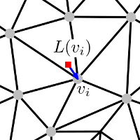
The Laplacian representation (referred to as Laplace coordinates in [2]) of a vertex in a surface mesh is one way to encode the local neighborhood of a vertex in the surface mesh. In this representation, a vertex \( \mathbf{v}_i \) is associated a 3D vector defined as:

\begin{equation} L(\mathbf{v}_i) = \sum_{\mathbf{v}_j \in N(\mathbf{v}_i)} w_{ij}(\mathbf{v}_i - \mathbf{v}_j), \label{eq:lap_open} \end{equation}

where:

  • \(N(\mathbf{v}_i)\) denotes the set of vertices adjacent to \(\mathbf{v}_i\);
  • \(w_{ij}\) denotes a weight for the directed edge \(\mathbf{v}_i\ \mathbf{v}_j\).

The simplest choice for the weights is the uniform scheme where \( w_{ij}=1/|N(\mathbf{v}_i)| \) for each adjacent vertex \(\mathbf{v}_j\). In this case, the Laplacian representation of a vertex is the vector between this vertex and the centroid of its adjacent vertices (Figure 69.7).

In the surface mesh deformation context, a popular choice is the cotangent weight scheme that derives from the discretization of the Laplace operator [5] : Given an edge of the surface mesh, its corresponding cotangent weight is the mean of the cotangents of the angles opposite to the edge. It was shown to produce results that are not biased by the surface mesh of the approximated surface [6].

simple_mesh_with_laplacian.png
Figure 69.7 Laplacian representation of \( v_i \) with uniform weights: the red square vertex is the centroid of the vertices adjacent to \( v_i \). The Laplacian representation \( L(v_i) \) is represented as a blue vector.

Considering a surface mesh with \(n\) vertices, it is possible to define its Laplacian representation \(\Delta\) as a \(n \times 3\) matrix:

\begin{equation} \mathbf{L}\mathbf{V} = \Delta, \label{eq:lap_system} \end{equation}

where:

  • \(\mathbf{L}\) is a \(n \times n\) sparse matrix, referred to as the Laplacian matrix. Its elements \( m_{ij} \), \(i,j \in \{1 \dots n\} \) are defined as follows:
    • \( m_{ii} \) = \( \sum_{\mathbf{v}_j \in N(\mathbf{v}_i)}w_{ij} \),
    • \( m_{ij} = -w_{ij} \) if \( \mathbf{v}_j \in N(\mathbf{v_i}) \),
    • \( 0 \) otherwise.
  • \(\mathbf{V}\) is a \(n \times 3\) matrix made of the Cartesian coordinates of the vertices.

Laplacian Deformation

This section is an introduction to provide the background for the next two sub-sections describing the algorithms implemented in this package. A system relying only on the approach described below results in non-smooth transitions in the neighborhood of the control vertices. For a survey on different Laplacian-based editing techniques we refer to [1].

The main idea behind Laplacian-based deformation techniques is to preserve the Laplacian representation under deformation constraints. The Laplacian representation of a surface mesh is treated as a representative form of the discretized surface, and the deformation process must follow the deformation constraints while preserving the Laplacian representation as much as possible.

There are different ways to incorporate deformation constraints into the deformation system [1]. This package supports hard constraints, that is, target positions of control vertices are preserved after the deformation.

Given a surface mesh deformation system with a ROI made of \( n \) vertices and \( k \) control vertices, we consider the following linear system:

\begin{equation} \left[ \begin{array}{ccc} \mathbf{L}_f\\ 0 \; \mathbf{I}_c \end{array} \right] \mathbf{V} = \left[ \begin{array}{ccc} {\Delta}_f \\ \mathbf{V}_c \end{array} \right], \label{eq:lap_energy_system} \end{equation}

where:

  • \(\mathbf{V}\) is a \(n \times 3\) matrix denoting the unknowns of the system that represent the vertex coordinates after deformation. The system is built so that the \( k \) last rows correspond to the control vertices.
  • \(\mathbf{L}_f\) denotes the Laplacian matrix of the unconstrained vertices. It is a \( (n-k) \times n \) matrix as defined in Eq. \(\eqref{eq:lap_system}\) but removing the rows corresponding to the control vertices.
  • \(\mathbf{I}_c\) is the \(k \times k\) identity matrix.
  • \({\Delta}_f\) denotes the Laplacian representation of the unconstrained vertices as defined in Eq. \(\eqref{eq:lap_system}\) but removing the rows corresponding to the control vertices.
  • \(\mathbf{V}_c\) is a \(k \times 3\) matrix containing the Cartesian coordinates of the target positions of the control vertices.

The left-hand side matrix of the system of Eq. \(\eqref{eq:lap_energy_system}\) is a square non-symmetric sparse matrix. To solve the aforementioned system, an appropriate solver (e.g. LU solver) needs to be used. Note that solving this system preserves the Laplacian representation of the surface mesh restricted to the unconstrained vertices while satisfying the deformation constraints.

As-Rigid-As Possible Deformation

Given a surface mesh \(M\) with \( n \) vertices \( \{\mathbf{v}_i\} i \in \{1 \dots n \} \) and some deformation constraints, we consider the following energy function:

\begin{equation} \sum_{\mathbf{v}_i \in M} \sum_{\mathbf{v}_j \in N(\mathbf{v}_i)} w_{ij} \left\| (\mathbf{v}'_i - \mathbf{v}'_j) - \mathbf{R}_i(\mathbf{v}_i - \mathbf{v}_j) \right\|^2, \label{eq:arap_energy} \end{equation}

where:

  • \(\mathbf{R}_i\) is a \( 3 \times 3 \) rotation matrix
  • \(w_{ij}\) denotes a weight
  • \(N(\mathbf{v}_i)\) denotes the set of vertices adjacent to \(\mathbf{v}_i\) in \(M\)
  • \(N(\mathbf{v}'_i)\) denotes a new position of the vertex \(N(\mathbf{v}_i)\) after a given deformation

An as-rigid-as possible surface mesh deformation [6] is defined by minimizing this energy function under the deformation constraints, i.e. the assigned position \( {v}'_i\) for each vertex \( \mathbf{v}_i\) in the set of control vertices. Defining the one-ring neighborhood of a vertex as its set of adjacent vertices, the intuitive idea behind this energy function is to allow each one-ring neighborhood of vertices to have an individual rotation, and at the same time to prevent shearing by taking advantage of the overlapping of one-ring neighborhoods of adjacent vertices (see Figure 69.8).

overlapping_cells.png
Figure 69.8 Overlaps of one-ring neighborhoods of vertices. The one-ring neighborhoods of four vertices are drawn with different colors, the corresponding vertex is colored accordingly.

There are two unknowns per vertex in Eq. \(\eqref{eq:arap_energy}\): the new positions ( \(\mathbf{v}'_k\)) of the unconstrained vertices and the rotation matrices ( \(\mathbf{R}_i\)). If the energy contribution of each vertex is positive, this boils down to minimizing the energy contribution of each vertex \(\mathbf{v}_i\).

Each such term of the energy is minimized by using a two-step optimization approach (also called local-global approach).

In the first step, the positions of the vertices are considered as fixed so that the rotation matrices are the only unknowns.

For the vertex \(\mathbf{v}_i\), we consider the covariance matrix \(\mathbf{S}_i\):

\begin{equation} \mathbf{S}_i = \sum_{\mathbf{v}_j \in N(\mathbf{v}_i)} w_{ij} (\mathbf{v}_i - \mathbf{v}_j)(\mathbf{v}'_i - \mathbf{v}'_j)^T, \label{eq:cov_matrix} \end{equation}

It was shown [7] that minimizing the energy contribution of \(\mathbf{v}_i\) in Eq. \(\eqref{eq:arap_energy}\) is equivalent to maximizing the trace of the matrix \(\mathbf{R}_i \mathbf{S}_i\). \(\mathbf{R}_i \) is the transpose of the unitary matrix in the polar decomposition of \(\mathbf{S}_i\).

In the second step, the rotation matrices are substituted into the partial derivative of Eq. \(\eqref{eq:arap_energy}\) with respect to \(\mathbf{v}'_i\). Assuming the weights are symmetric, setting the derivative to zero results in the following equation:

\begin{equation} \sum_{\mathbf{v}_j \in N(\mathbf{v}_i)} w_{ij}(\mathbf{v}'_i - \mathbf{v}'_j) = \sum_{\mathbf{v}_j \in N(\mathbf{v}_i)} w_{ij} \frac{(\mathbf{R}_i + \mathbf{R}_j)}{2} (\mathbf{v}_i - \mathbf{v}_j). \label{eq:lap_ber} \end{equation}

The left-hand side of this equation corresponds to the one of Eq. \(\eqref{eq:lap_open}\), and we can set \(\Delta\) to be the right-hand side. Solving the linear system in Eq. \(\eqref{eq:lap_energy_system}\) gives the new positions of the unconstrained vertices.

This two-step optimization can be applied several times iteratively to obtain a better result.

Note
The matrix built with the Laplacian matrix of the unconstrained vertices in the left-hand side of Eq. \(\eqref{eq:lap_energy_system}\) depends only on the initial surface mesh structure and on which vertices are control vertices. Once the control vertices are set, we can use a direct solver to factorize the sparse matrix in Eq. \(\eqref{eq:lap_energy_system}\), and reuse this factorization during each iteration of the optimization procedure.

The original algorithm [6] we described assumes that:

  • the weight between two vertices is symmetric. In order to support asymmetric weights in our implementation, we slightly change Eq. \(\eqref{eq:lap_ber}\) to:

    \begin{equation} \sum_{\mathbf{v}_j \in N(\mathbf{v}_i)} (w_{ij} + w_{ji})(\mathbf{v}'_i - \mathbf{v}'_j) = \sum_{\mathbf{v}_j \in N(\mathbf{v}_i)} (w_{ij}\mathbf{R}_i + w_{ji}\mathbf{R}_j)(\mathbf{v}_i - \mathbf{v}_j). \label{eq:lap_ber_asym} \end{equation}

  • The energy contribution of each vertex is positive. If the weight between two vertices is always positive, this is always the case. However, when using the cotangent weighting scheme (the default in our implementation), if the sum of the angles opposite to an edge is greater than \( \pi \), its cotangent weight is negative. As a workaround for bad quality meshes, we eliminate those negative weights by setting them to zero.

A method minimizing another energy function is described next to avoid the latter issue.

Spokes and Rims Version

The elastic energy function proposed by [3] additionally takes into account all the opposite edges in the facets incident to a vertex. The energy function to minimize becomes:

\begin{equation} \sum_{\mathbf{v}_i \in M} \sum_{(\mathbf{v}_j, \mathbf{v}_k) \in E(\mathbf{v}_i)} w_{jk} \left\| (\mathbf{v}'_j - \mathbf{v}'_k) - \mathbf{R}_i(\mathbf{v}_j - \mathbf{v}_k) \right\|^2, \label{eq:arap_energy_rims} \end{equation}

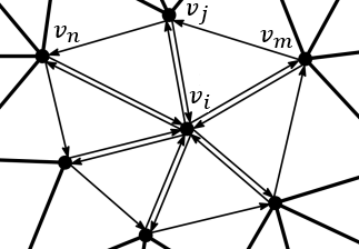
where \(E(\mathbf{v}_i)\) consists of the set of edges incident to \(\mathbf{v}_i\) (the spokes) and the set of edges in the link (the rims) of \(\mathbf{v}_i\) in the surface mesh \(M\) (see Figure 69.9).

spoke_and_rim_edges_2.png
Figure 69.9 The vertices \( \mathbf{v}_n\) and \( \mathbf{v}_m\) are the opposite vertices to the edge \( \mathbf{v}_i \mathbf{v}_j\).

The method to get the new positions of the unconstrained vertices is similar to the two-step optimization method explained in As-Rigid-As Possible Deformation. For the first step, the Eq. \(\eqref{eq:cov_matrix}\) is modified to take into account the edges in \(E(\mathbf{v}_i)\):

\begin{equation} \mathbf{S}_i = \sum_{(\mathbf{v}_j, \mathbf{v}_k) \in E(\mathbf{v}_i)} w_{jk} (\mathbf{v}_j - \mathbf{v}_k)(\mathbf{v}'_j - \mathbf{v}'_k)^T, \label{eq:cov_matrix_sr} \end{equation}

For the second step, setting partial derivative of Eq. \(\eqref{eq:arap_energy_rims}\) to zero with respect to \(\mathbf{v}_i\) gives the following equation:

\begin{equation} \sum_{\mathbf{v}_j \in N(\mathbf{v}_i)} (w_{ij} + w_{ji})(\mathbf{v}'_i - \mathbf{v}'_j) = \sum_{\mathbf{v}_j \in N(\mathbf{v}_i)} \frac{w_{ij}(\mathbf{R}_i + \mathbf{R}_j + \mathbf{R}_m) + w_{ji}(\mathbf{R}_i + \mathbf{R}_j + \mathbf{R}_n)}{3} (\mathbf{v}_i - \mathbf{v}_j). \label{eq:lap_ber_rims} \end{equation}

where \(\mathbf{R}_m\) and \(\mathbf{R}_n\) are the rotation matrices of the vertices \(\mathbf{v}_m\), \(\mathbf{v}_n\) which are the opposite vertices of the edge \(\mathbf{v}_i \mathbf{v}_j\) (see Figure 69.9). Note that if the edge \( \mathbf{v}_i \mathbf{v}_j \) is on the boundary of the surface mesh, then \( w_{ij} \) must be 0 and \( \mathbf{v}_m \) does not exist.

An important property of this approach compared to As-Rigid-As Possible Deformation is that the contribution to the global energy of each vertex is guaranteed to be non-negative when using the cotangent weights [3]. Thus even with negative weights, the minimization of the energy with the iterative method presented is always guaranteed. However, this method is more dependent on the discretization of the deformed surface (See Figure 69.2).

The implementation in this package uses the cotangent weights by default (negative values included) as proposed in [3].

Smoothed Rotation Enhanced As-Rigid-As Possible (SR_ARAP) Deformation

Using 1-ring elements, SR-ARAP adds a bending element to Eq. \(\eqref{eq:arap_energy}\):

\begin{equation} \sum_{\mathbf{v}_i \in M} \sum_{\mathbf{v}_j \in N(\mathbf{v}_i)} w_{ij} \left\| (\mathbf{v}'_i - \mathbf{v}'_j) - \mathbf{R}_i(\mathbf{v}_i - \mathbf{v}_j) \right\|^2 + \alpha A \left\| \mathbf{R}_i - \mathbf{R}_j \right\|^2_F \label{eq:sre_arap_energy} \end{equation}

where

  • \(\alpha=0.02\) is a weighting coefficient.
  • \(A\) is the surface area for scaling invariance.

Only the local step is influenced by the added term, and the optimal rotation now takes into account the rotation of neighbors.

Design and Implementation History

An initial version of this package has been implemented during the 2011 Google Summer of Code by Yin Xu under the guidance of Olga Sorkine and Andreas Fabri. Ilker O. Yaz took over the finalization of the package with the help of Sébastien Loriot for the documentation and the API. In 2016, Zohar Levi and Sébastien Loriot extended the package to support Smoothed Rotation Enhanced ARAP. The authors are grateful to Gaël Guennebaud for his great help on using the Eigen library and for providing the code to compute the closest rotation.